
Subscribe to Our Youtube Channel
Related Manuals for Northern Lights LUGGER M6108


Summary of Contents for Northern Lights LUGGER M6108
- Page 1 O6108 For Models: M6108, NL6108, and L6108 OPERATOR’S MANUAL Marine Generators | Marine Diesel Engines | Land-Based Generators...
- Page 2 4420 14th Avenue N.W. Seattle, WA 98107 Tel: (206) 789-3880 Fax: (206) 782-5455 Copyright ©2001 Northern Lights, Inc. All rights reserved. Northern Lights™, and the Northern Lights logo are trademarks of Northern Lights, Inc. Printed in U.S.A. PART NO.: O6108 08/01...
-
Page 3: Table Of Contents
This publication is the property of Northern Lights, Inc. It may not be reproduced in whole or in part without the written permission of Northern Lights, Inc. © Northern Lights, Inc. All rights reserved. Litho U.S.A. Publication number O6108 08/01... -
Page 4: Introduction
A, D, T, & Q L - Lugger marine propulsion engine Model number of A - Aftercooled (turbo) M - Northern Lights marine generator set Komatsu engine block D - Naturally aspirat NL - Northern Lights industrial generator set 6 cylinder, 108 mm bore... -
Page 5: Warranty
Warranty A warranty registration certifi cate is supplied If the warranty is to apply, the servicing with your set. It entitles the original purchaser instructions outlined in this manual must be of this equipment to a warranty covering mate- followed. If further information is needed, rial or assembly faults. -
Page 6: Component Locations Northern Lights Marine Generator
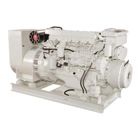
Marine Generator Set Component Locations Figure 3. M6108A Generator Set Expansion tank Exhaust manifold drain Dipstick Coolant Filter Coolant fi ll (behind hose) Raw Water Pump Block Drain Vapor trap valve cover Wet exhaust elbow Raw Water Drain Lube Oil Filter Lube oil fi... -
Page 7: Lugger Marine Propulsion Engines
Marine Propulsion Engine Component Locations Figure 4. L6108A2, keel cooled Expansion Tank Exhaust Manifold drain Engine Oil Cooler D.C. Circuit Breaker and Coolant Fill Secondary Fuel Filter Gear Oil Cooler drain relays Vapor Trap Valve Cover Starter Manual Fuel Prime Pump Low Water Level Gauge Lube Oil Fill Fuel Injection Pump... -
Page 8: Northern Lights Industrial Generator
Northern Lights Industrial Engine Component Locations Figure 5. NL6108 Solenoid Alternator Generator Junction Box Air Cleaner Fuel Return Line Dipstick Fuel Inlet Line Oil Fill Fuel Filter Corrosion Resister Oil Filter Starter (behind Fuel/Water Exhaust Elbow Coolant Fill Separator) Fuel/Water Separator... - Page 9 Notes O6108 08/01...
-
Page 10: Control Panels Northern Lights Generator Sets
Control Panels - Northern Lights Generator Sets 1. SHUTDOWN BYPASS PREHEAT SERIES 3 GENERATOR CONTROL PANEL SWITCH: Two functions are built into this switch: The preheating of the engine, and bypassing of the engine safety shutdown circuit, enabling a quicker start. Hold switch in up position 10-20 seconds before starting engine, and continue holding in up position while starting engine. -
Page 11: Lugger Marine Propulsion Engines
Control Panels - Lugger Marine Propulsion Engines 1. OIL PRESSURE GAUGE: 8. INSTRUMENT LIGHTING DIMMER: The oil pressure gauge shows the oil pressure in Adjust instrument panel lights. (On some panels the engine lubricating system. If the oil pres- this is an on/off switch and not a dimmer.) sure drops BELOW 15 PSI at a speed higher 9. -
Page 12: Operating Procedures
Operating Procedures BEFORE STARTING Operating 1. Check Gauges Often: Oil pressure must be 1. Check the water level by removing the pressure above 29 PSI. The DC voltmeter should read cap from the expansion tank. In order to give the between 13 and 14 volts (26-28 volts, 24 volt cooling water an opportunity to expand, the level systems) at 60... -
Page 13: Shutdowns And Alarms
NOTE: Do not turn battery switch to OFF while c. If the oil level is normal, DO NOT restart the engine is running. engine. Call your Northern Lights or Lugger SHUTDOWNS AND ALARMS dealer for assistance. 1. Your unit is fi tted with a system to protect it BREAK-IN PERIOD from high water temperature or low oil pressure. -
Page 14: Servicing Schedule Chart
Servicing Schedule Chart The Servicing Schedule Chart below shows the service schedule required for proper maintenance of your unit. More detailed coverage of each Service Point (SP) is listed on the page noted in the 'page' column. DAILY: EVERY 250 HOURS (Continued) Check oil level in engine Change primary fuel fi... - Page 15 Service Record Service OPERATION HOURS/DATE Point 50 HOURS (or weekly) Check V-belt tension SP25 Check electrolyte in batteries 250 HOURS (or every 6 months) Change engine oil Change lubricating oil fi lter Check air cleaner Change primary fuel fi lter element SP12 Check turbocharger air, oil &...
-
Page 16: Servicing
Servicing c. Turn pump handle in clockwise direction LUBRICATION - GENERAL and pump oil into a suitable container. 1. Use only clean, high quality lubricants When the engine is empty, switch the valve stored in clean containers in a protected area. and drain the gear oil. -
Page 17: Changing Oil Filter
Servicing SP4. AIR FILTER 4. Adjust the valve clearance for valves marked with 1. Inspect air cleaner every 250 hours, replace an “X” in Fig. 11. the fi lter every 750 hours, or yearly, whichever 5. Rotate the crankshaft in clockwise direction one comes fi... -
Page 18: Fuel Filters
fi lter manufacturer. Empty 1. Fuel injectors should be checked by a Lugger- the collection bowl as necessary. Northern Lights dealer or qualifi ed fuel injection b. Change the element every 250 hours or when shop after every 750 hours. -
Page 19: Injection Pump
Servicing b. Reinstall bracket between the engine block SP11. INJECTION PUMP and rear of pump. Leave pump mounting nut 1. The pump settings, maximum speed, idle speed (see Fig. 12,8) loose until pump is timed. and exhaust smoke should be checked after c. - Page 20 Servicing TIMING INJECTION PUMP d. Use a breaker bar with the appropriate socket to rotate the crankshaft in a clockwise direc- 1. The Match Mark Alignment Method: tion while operating the priming pump (12,6). Note: This is used when the injection pump is being This is best done by two people.
-
Page 21: Turbocharger
Servicing h. Align the injection timing line (as speci- fi ed in the Technical manual or on the data plate on the engine) on the damper with the pointer by slowly rotating the crankshaft in the clockwise direction. Figure 14. Injection Pump Coupler SP12. -
Page 22: Cooling System Requirements
Servicing COOLING REQUIREMENTS LINER EROSION (PITTING) 1. To meet cooling system protection requirements, 1. Cylinder liner walls (A) which are in contact the coolant solution must consist of: with engine coolant (B) can be eroded or pitted a. Quality water unless the proper concentration and type of SCA's are present in the coolant. - Page 23 Servicing CAUTION: EGC (Antifreeze) is fl ammable. 4. If total hardness is higher than 170 ppm and all Keep it away from any open fl ame. Avoid other parameters are within the given specifi ca- contact with eyes. Avoid contact with skin. tions, the water must be softened before it is used Do not take internally.
-
Page 24: Checking Coolant Level
You SCA concentration meets recommended levels. must use extreme caution when working on 5. SCA is available from your Northern Lights/ hot engines to avoid burns. Allow the engine Lugger dealer in the following sizes. Pint - Part Number....20-00002 to cool before working on the cooling system. -
Page 25: Heat Exchanger Cleaning (Marine)
Follow service rec- leaks. ommendations closely. 2. If you have a Northern Lights generator set, the maintenance and operation recommendations for the generator end are in a separate Owner's Manual. If you do not have one of these manu- als, contact your local Northern Lights dealer. -
Page 26: Glow Plugs
Servicing 5. Remove booster battery after starting engine. ELECTRICAL SYSTEM - GENERAL 6. Sealed batteries: see manufacturer charging and 1. Never switch battery switch off or break the booster instruction. circuit between the alternator and batteries while the engine is running. Regulator damage can P24,25. -
Page 27: Propeller Sizing Chart
Three Bladed Propeller Sizing Chart 1) Find the boat speed your boat builder expects from an Use this chart to fi nd aproximate propeller sizes for boats engine of this horsepower in the left column. with single engine using a three blade propeller and gears 2) Locate the gear ratio desired on the top line. -
Page 28: Data Sheets
Northern Lights Marine Specifi cations Model M6108QA2 M6108QA2 M6108T2 M6108T2 M6108A2 M6108A2 1200 1200 1500 1800 1500 1800 Frequency (Hz) Engine Displacement cu. in.( 436 (7.15) 436 (7.15) 436 (7.15) 436 (7.15) 436 (7.15) 436 (7.15) Bore - in (mm) 4.25 (108) -
Page 29: L6108
Lugger Specifi cations General Specifi cations Stroke ...........5.12 in (130mm) Model Number ..........L6108A2 Aspiration...... Turbocharged/Aftercooled Cylinders.............. Inline 6 Approx. dry weight, less gear, with Displacement ........436 in (7.145 liters) keel cooling ......1622 lbs (735 kg) Operating Cycle .............4 heat exchanger ...... - Page 30 • Clean and tighten battery and harness plug connections. Sulfated or worn out batteries • Check specifi c gravity and electrolyte level of each battery. If you cannot correct problems with these procedures, see your Lugger or Northern Lights dealer. O6108 08/01...
-
Page 31: Engine
Improper type of fuel • Consult fuel supplier and use proper type of fuel for operating condition. If you cannot correct problems with these procedures, see your Lugger or Northern Lights dealer. O6108 08/01... - Page 32 • Remove paint from tubes. have been painted (marine) Cooling system needs fl ushing • Flush cooling system. Defective thermostat • Remove and check thermostat. If you cannot correct problems with these procedures, see your Lugger or Northern Lights dealer. O6108 08/01...
- Page 33 • Use proper viscosity oil. Oil leaks • Check for leaks in lines around gaskets and drain plug. Engine overheats • See “Engine Overheats” in category above. If you cannot correct problems with these procedures, see your Lugger or Northern Lights dealer. O6108 08/01...
- Page 34 • Warm up engine to normal operating temperature. Defective thermostat • Remove and check thermostat. Engine out of time • See your dealer. If you cannot correct problems with these procedures, see your Lugger or Northern Lights dealer. O6108 08/01...
-
Page 35: Dc Wiring Diagrams
Wiring Diagrams O6108 08/01... -
Page 36: 12 Volt Nl Marine Generator
Wiring Diagrams O6108 08/01... - Page 37 Wiring Diagrams O6108 08/01...
- Page 38 Wiring Diagrams O6108 08/01...
- Page 39 Wiring Diagrams O6108 08/01...
-
Page 40: 12 Lugger Propulsion Engine
Wiring Diagrams O6108 08/01... - Page 41 Wiring Diagrams O6108 08/01...
-
Page 42: On-Board Spare Parts Kit
On-Board Spare Parts Kit Safety at sea depends on careful preparation, product knowledge, and having the right tools and parts. Below is a list of parts Northern Lights, Inc. recommends you carry onboard at all times. Onboard Parts Kits are available from your dealer. "Standard" Kits are suitable for inland and offshore cruising. - Page 43 4420 14th Ave. NW., Seattle WA 98107 Tel: (206) 789-3880 • 1-800-762-0165 • Fax: (206) 782-5455 Northern Lights and Lugger are registered trademarks of Northern Lights, Inc. www.northern-lights.com © 2001 All rights reserved. Litho USA.
Need help?
Do you have a question about the LUGGER M6108 and is the answer not in the manual?
Questions and answers