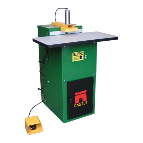
CASTLE TSM-21 Diagnostic Manual
Pocket hole machine with parker or humphrey solenoids
Hide thumbs
Also See for TSM-21:
- Diagnostic manual (63 pages) ,
- Installation instructions manual (25 pages)

Subscribe to Our Youtube Channel
Related Manuals for CASTLE TSM-21


Summary of Contents for CASTLE TSM-21
- Page 1 CASTLE, INC. Diagnostic Manual TSM-21 Pocket Hole Machine with Parker or Humphrey Solenoids Serial numbers 61076 and above CASTLE INC PO BOX 750236 PETALUMA CA 94975 WWW.CASTLEUSA.COM...
-
Page 2: Table Of Contents
5.11 21.31..................32 OUTER HECK OLENOID 5.12 21.32 ................33 OUTER DJUSTMENT 5.13 21.40 ..................35 RILL OTOR PERATION 5.14 21.41 ................36 RILL ETTINGS AND EPTH 5.15 21.42 ................38 RILL INGLE PRING Castle Inc TSM-21 Diagnostic Manual Parker/Humphrey Solenoids Page 2 of 67... - Page 3 PERATORS APPENDIX B – WIRING DIAGRAM 21.84 ................63 APPENDIX C – CONTROL BOX WORKS 21.93 ...............64 APPENDIX D – SOLENOID, PNEUMATIC DIAGRAM 21.94 ............65 APPENDIX E – INDEX .........................66 Castle Inc TSM-21 Diagnostic Manual Parker/Humphrey Solenoids Page 3 of 67...
-
Page 4: Introduction
1 Introduction Thank you for making the Castle TSM-21 Screw Pocket Machine a vital part of your shop. The TSM-21 is designed for use on a wide variety of materials including hardwoods, softwoods, melamine, particleboard and MDF. This manual is intended for anyone working with, or performing maintenance or service on the TSM-21. -
Page 5: How To Use This Manual
21.11 12-13 Note: If you are unsure of your observations or if the fault behaviour seems irregular you should “Dry Cycle” test the machine. See Procedure 21.95, page 4. Castle Inc TSM-21 Diagnostic Manual Parker/Humphrey Solenoids Page 5 of 67... -
Page 6: Dry Cycle Testing 21.95
2 Dry Cycle Testing 21.95 2.1 Purpose Dry Cycle testing allows observation of the TSM-21’s mechanical, electrical, and pneumatic functions without routing pockets or drilling holes. Caution: Careful observation is essential when troubleshooting or seeking Technical Support 2.2 Dry Test TSM-21 Locate the ON/OFF switches on the Router and Drill and turn them both off or uplug the routers. - Page 7 The carriage plate should land in between the switch and the magnet. Castle Inc TSM-21 Diagnostic Manual Parker/Humphrey Solenoids Page 7 of 67...
-
Page 8: Manual Override Of Solenioids
1. Remove the air line out fitting and the exhaust muffler and press the override button for several seconds. Air should flow through the solenoid. Reassemble and cut a test pocket. See FIG. 1a and 1b. Fig 1a Fig 1b Castle Inc TSM-21 Diagnostic Manual Parker/Humphrey Solenoids Page 8 of 67... -
Page 9: Definitions
Controls the speed at which the Pocket Router moves through the Valve material when cutting the Pocket. Note: Should be adjusted AFTER the main operational speed of the machine has been set with the Air Pressure Regulator. Castle Inc TSM-21 Diagnostic Manual Parker/Humphrey Solenoids Page 9 of 67... - Page 10 Safety Switch Normally CLOSED (NC) switches Router Stop Switch Drill Stop Switch The distance between the deepest part of the pocket and the edge of the material. Castle Inc TSM-21 Diagnostic Manual Parker/Humphrey Solenoids Page 10 of 67...
-
Page 11: Diagnostic Descriptions
□ Internal Air Pressure too low, adjust Pressure regulator………… 21.90 □ Router Feed Speed too fast, adjust Router Feed Rate………….. 21.32 □ Check Tooling, may be dull………………………………………… 21.83 □ Check Clamp Solenoid for blockage……………………..….. 21.10 Castle Inc TSM-21 Diagnostic Manual Parker/Humphrey Solenoids Page 11 of 67... - Page 12 □ □ Check Bar Spring position......……………………. 21.42 Clamp doesn’t release…Machine Routs but Router DOES NOT retract, DOES NOT Drill: 21.43 □ Router Stop switch…………………………………………………. □ □ Check Bar Spring position........……………...…… 21.42 Castle Inc TSM-21 Diagnostic Manual Parker/Humphrey Solenoids Page 12 of 67...
-
Page 13: Router Operation
....……………………………………… 21.60 □ Exhaust ……..………….………… 21.61 □ ………………………...… . ………… 21.42 Router advances too aggressively: □ Adjust internal Air Pressure…………………………...…………… 21.90 □ Adjust the Router Feed Rate Valve...……………………..……… 21.32 Castle Inc TSM-21 Diagnostic Manual Parker/Humphrey Solenoids Page 13 of 67... - Page 14 Check Router Feed Rate may be turned all the way down……..21.32 □ Router Solenoid for function or blockage………..…… 21.31 □ Drive Cylinder for leaks....…………………………… 21.60 □ for Blockage in Drill Solenoid Exhaust Muffler..………… 21.61 Castle Inc TSM-21 Diagnostic Manual Parker/Humphrey Solenoids Page 14 of 67...
-
Page 15: Drill Operation
□ Adjust air pressure, Machine cycling too slowly………………….. 21.90 □ Bit mounted too deep into collet……………………………………. 21.41 □ Check for inconsistent web depth-See Router Stop Switch...,..21.22 □ Check Tooling, may be dull............21.83 Castle Inc TSM-21 Diagnostic Manual Parker/Humphrey Solenoids Page 15 of 67... -
Page 16: Overall Machine Operation And Pocket Adjustment
□ Adjust Air Pressure Regulator……………………………………… 21.90 □ Check Drive cylinder for air leak…………………………………… 21.60 □ Check for other air driven machines on the same line…………... 21.90 □ Check Exhaust Mufflers for blockage......…………... 21.61 Castle Inc TSM-21 Diagnostic Manual Parker/Humphrey Solenoids Page 16 of 67... - Page 17 21.72 □ Check Drill motor mounting………………………………………… 21.40 Pocket too close or too far from the edge of the stock, WEB adjustment: □ Adjust Web with Router Stop Plate………………………………... 21.21 Castle Inc TSM-21 Diagnostic Manual Parker/Humphrey Solenoids Page 17 of 67...
-
Page 18: Procedures
Clamp Foot and break it free of thread lock com- pound. See Fig 2. Jamb Nut Clamp Foot Foot Pad Fig 2 Castle Inc TSM-21 Diagnostic Manual Parker/Humphrey Solenoids Page 18 of 67... -
Page 19: Unclogging The Clamp Solenoid 21.10
Note: To remove the air line from the clamp cylinder, push in the plastic or metal rim of the fitting and pull the air line out. To re-install, push the air line in until it meets resistance and then push in another 1/2'”. Fig 3a Castle Inc TSM-21 Diagnostic Manual Parker/Humphrey Solenoids Page 19 of 67... - Page 20 4. Reconnect power. Cut a test pocket. Note: If this procedure does not correct the problem, the Clamp Solenoid will need to be replaced. Refer to Procedure 21.91, "Replacing Solenoids". Castle Inc TSM-21 Diagnostic Manual Parker/Humphrey Solenoids Page 20 of 67...
-
Page 21: Clamp Solenoid Check 21.11
3. If the clamp does not extend, lift the work top of the machine Locate the manual overide button on the clamp solenoid. See Fig 4a and Fig 4b Fig 4a Castle Inc TSM-21 Diagnostic Manual Parker/Humphrey Solenoids Page 21 of 67... - Page 22 If the clamp cylinder does not extend, then the Clamp Solenoid may be stuck closed or clogged. If the Clamp Solenoid is stuck open/closed or clogged, Perform procedure 21.10, Unclogging the Clamp Solenoid. Castle Inc TSM-21 Diagnostic Manual Parker/Humphrey Solenoids Page 22 of 67...
-
Page 23: Clamp Cylinder Check 21.12
5. If both clamp actions are smooth and quick the Clamp Cylinder is operating properly. Continue troubleshooting the Clamp Cylinder Air Line, the Exhaust Muffler on the Clamp Solenoid and the Clamp Solenoid. See Fig 5b and 5c. Castle Inc TSM-21 Diagnostic Manual Parker/Humphrey Solenoids Page 23 of 67... -
Page 24: Clamp Exhaust Check 21.13
Exhaust Muffler on the Exhaust Port may be blocked. 5.5.1 TROUBLESHOOTING STEPS: 1. Open the rear door. The Exhaust muffler is the brass fitting located next to the air inlet on the clamp solenoid. See Fig 6. Castle Inc TSM-21 Diagnostic Manual Parker/Humphrey Solenoids Page 24 of 67... - Page 25 Note: It is never recommended to run the machine without exhaust mufflers as sawdust can be pulled back into solenoid valve and cause issues. Castle Inc TSM-21 Diagnostic Manual Parker/Humphrey Solenoids Page 25 of 67...
-
Page 26: Router Motor Operation 21.20
4. With your right hand loosen the Router T-Knob a few turns to provide enough slack to drop the Router Motor down into your left hand and then out the rear door. Castle Inc TSM-21 Diagnostic Manual Parker/Humphrey Solenoids Page 26 of 67... - Page 27 2. The Router motor is warranted for one year from the purchase of the machine. 3. Warranty replacement and parts purchases can be handled by your nearest Porter Cable/ Bosch dealer or service center, or Castle. 4. The Router Motor has two electrical brushes that should be periodically replaced. See Fig 8.
-
Page 28: Adjusting The Web , Router Stop Plate 21.21
Web. 4. Secure the lock nut after making any adjustments. Castle Inc TSM-21 Diagnostic Manual Parker/Humphrey Solenoids Page 28 of 67... -
Page 29: Router Stop Switch (Nc) 21.22
2. The Router Stop Switch and Magnet are attached to the back side of the Router Stop Plate, which is located just to the left of the Drill motor. See Fig 10. Router Stop Switch Router Stop Plate Router Stop Magnet Fig 10 Castle Inc TSM-21 Diagnostic Manual Parker/Humphrey Solenoids Page 29 of 67... - Page 30 Note: If a dry cycle is preformed to confirm function of the switch and the router bit stays extended, verify that the carriage plate is not hitting the front of the switch/magnet. The carriage plate should land in between the switch and the magnet. Castle Inc TSM-21 Diagnostic Manual Parker/Humphrey Solenoids Page 30 of 67...
-
Page 31: Unclogging The Router Solenoid 21.30
Rule of Thumb: Router feed speed should be as fast as possible while still maintaining smooth,clean, straight pockets.feepeed should be as fast as possible while still maintaining smooth, clean, straight pockets. Castle Inc TSM-21 Diagnostic Manual Parker/Humphrey Solenoids Page 31 of 67... -
Page 32: Router Check Solenoid 21.31
2. If the router automatically extends, then the Router Solenoid is stuck open. 3. If the router does not extend, ffrom the rear door, locate the manual override button on the router solenoid. See Fig 12a and Fig 12b FIG. 12a Castle Inc TSM-21 Diagnostic Manual Parker/Humphrey Solenoids Page 32 of 67... -
Page 33: Router Feed Rate Adjustment 21.32
Router. Note: If the Pressure Regulator has been adjusted, readjust the Router Feed Rate (if necessary) AFTER the Pressure Regulator setting has been finalized. Castle Inc TSM-21 Diagnostic Manual Parker/Humphrey Solenoids Page 33 of 67... - Page 34 Router Feed Rate valve up slightly (counter clockwise). If the router moves slowly then the router feed valve should be OK. If the router comes up extremely fast, replace the router feed rate valve. Castle Inc TSM-21 Diagnostic Manual Parker/Humphrey Solenoids Page 34 of 67...
-
Page 35: Drill Motor Operation 21.40
Drill Motor Drill T-Knob Fig 14 3. Locate the Drill T-Knob on left side of the Motor Carriage. 4. Gently rock the Drill Motor as you tighten the T-Knob Castle Inc TSM-21 Diagnostic Manual Parker/Humphrey Solenoids Page 35 of 67... -
Page 36: Drill Settings And Bit Depth 21.41
4. The Drill Motor has two electrical brushes that should be periodically replaced. Note: During assembly at Castle, the front housing of the drill motor is rotated 90 degrees to orient the power cord straight down relative to the T-Knob bolt hole. Replacement motors obtained through sources other than Castle may need to have the front housing rotated similarly. - Page 37 “D” for Drill and “R” for Router. 2. The plate has two sides that can be used settings for different processes in the shop. Castle Inc TSM-21 Diagnostic Manual Parker/Humphrey Solenoids Page 37 of 67...
-
Page 38: Drill Single Coil Bar Spring 21.42
See Fig 16. Bar Spring Motor Carriage Carriage Bolt Fig 16 5. Make sure the Bar Spring is on the front side of the 3” carriage bolt and tighten the nuts. Castle Inc TSM-21 Diagnostic Manual Parker/Humphrey Solenoids Page 38 of 67... -
Page 39: Drill Stop Switch (Nc) 21.43
2. The Drill Stop Switch and magnet are located inside the machine on the back side of the Face Plate, slightly to the left of the Pilot Drill Hole. See Fig 17. Drill Stop Switch Motor Carriage Drill Stop Magnet Fig 17 Castle Inc TSM-21 Diagnostic Manual Parker/Humphrey Solenoids Page 39 of 67... - Page 40 9. If the switch needs to be replaced the laminate strip on the front of the machine may need to be removed to access the switch retaining screws. Pry the laminate free from the case with a sharpened putty knife. Contact Castle for a replacement laminate strip. Note:...
-
Page 41: Unclogging The Drill Solenoid 21.50
Air should flow through the solenoid. Press the override switch several more times for several seconds to throughly flush the solenoid. See Fig 18a and Fig 18b. Fig 18b Castle Inc TSM-21 Diagnostic Manual Parker/Humphrey Solenoids Page 41 of 67... - Page 42 3. Lower and secure the work top, then and reconnect power. Cut a test pocket. Note: If this procedure does not correct the problem, the Drill Solenoid will need to be re- placed. Refer to Procedure 21.91, “Replacing Solenoids”. Castle Inc TSM-21 Diagnostic Manual Parker/Humphrey Solenoids Page 42 of 67...
-
Page 43: Drill Solenoid Check 21.51
2. If the drill automatically extends, then the Drill Solenoid is stuck open. 3. If the drill does not extend, open rear door and locate the manual override button on the drill solenoid. See Fig 19a and Fig 19b. Fig 19a Castle Inc TSM-21 Diagnostic Manual Parker/Humphrey Solenoids Page 43 of 67... - Page 44 If the carriage does not tilt toward the front of the machine, then the Drill Solenoid may be stuck closed or clogged. If the Drill Solenoid is stuck open or clogged, Perform procedure 21.50, Unclogging the Drill Solenoid. Castle Inc TSM-21 Diagnostic Manual Parker/Humphrey Solenoids Page 44 of 67...
-
Page 45: Drive Cylinder Check 21.60
4. Listen for constant hissing and feel for leaking air at the exhaust ports of the Router Solenoid and the Drill Solenoid. See Fig 20a and 20b. Fig 20a Castle Inc TSM-21 Diagnostic Manual Parker/Humphrey Solenoids Page 45 of 67... - Page 46 6. Cycle the machine a few more times to see if the situation can be repeated. 7. If the stalled Drive Cylinder consistently leaks air, the cylinder must be replaced. Castle Inc TSM-21 Diagnostic Manual Parker/Humphrey Solenoids Page 46 of 67...
- Page 47 12. Cycle the machine a few more times to see if the situation can be repeated. 13. If the stalled Drive Cylinder consistently leaks air, the cylinder must be replaced. Castle Inc TSM-21 Diagnostic Manual Parker/Humphrey Solenoids Page 47 of 67...
-
Page 48: Exhaust Mufflers On Solenoid Valves 21.61
Mufflers as sawdust can be pulled back into solenoid valve and cause issues. 5.20.1 TESTING STEPS: 1. Open the rear door. Remove the exhaust mufflers from the Router and drill solenoids. See Fig 21. Fig 21 Castle Inc TSM-21 Diagnostic Manual Parker/Humphrey Solenoids Page 48 of 67... -
Page 49: Pilot Hole Alignment 21.72
Motor Carriage. See Fig 22. 2. Tightening the hex nut moves the drill tip left relative to the operator. Adjust accordingly. Misaligned Pilot hole Drill T-Knob Hex Nut Fig 22 Castle Inc TSM-21 Diagnostic Manual Parker/Humphrey Solenoids Page 49 of 67... -
Page 50: Foot Switch (No) 21.80
4. Use a flat or Phillips screwdriver to remove the two screws on the sides of the pedal and remove the top. See Fig 23. Spring Plate COM Terminal NC Terminals Fig 23 Castle Inc TSM-21 Diagnostic Manual Parker/Humphrey Solenoids Page 50 of 67... - Page 51 Note: A quick way to test the foot switch is to test for continuity on terminals 3 and 4 of the control board pressing down on the foot pedal. ONLY PERFORM THIS OPERATION WITH THE UNIT UNPLUGGED. Castle Inc TSM-21 Diagnostic Manual Parker/Humphrey Solenoids Page 51 of 67...
-
Page 52: Resetting The Machine 21.81
1. Disconnect power and air from the machine. 2. The reed switch and magnet are mounted on the case top to the right of the Drill Motor. See Fig 24. Castle Inc TSM-21 Diagnostic Manual Parker/Humphrey Solenoids Page 52 of 67... - Page 53 OPEN, the distance between the switch and magnet may need to be de- creased by 1/16”. 6. If the switch will not change from OPEN to CLOSED when the Safety Blade is raised de-spite adjustment, replace the switch and the magnet. Castle Inc TSM-21 Diagnostic Manual Parker/Humphrey Solenoids Page 53 of 67...
-
Page 54: Tooling Check And Replacement 21.83
6. When re-installing, make sure the motor face is pushed up to seat flush with the tabs on the yellow carriage (if unsure, remove table top to confirm location). Castle Inc TSM-21 Diagnostic Manual Parker/Humphrey Solenoids Page 54 of 67... - Page 55 8. Manually rock the Motor Carriage toward the front of the machine and make sure that the Drill Bit cleanly fits through the hole on the face plate. Fig 26 Castle Inc TSM-21 Diagnostic Manual Parker/Humphrey Solenoids Page 55 of 67...
-
Page 56: Air Pressure Regulator Setting 21.90
Note: It’s extremely important that a minimum 85 PSI be provided from your compressor. Operating pressure can be especially affected by other machines that share the same air line as your TSM-21. 5.26.1 TO RESET THE AIR PRESSURE REGULATOR: 1. -
Page 57: Replacing Solenoid Valves 21.91
3. Remove the two carriage bolts that hold the Control Box to the machine and pull the box partially out the rear door. See Fig 28. Carriage Bolts retaining the Control Box Fig 28 Castle Inc TSM-21 Diagnostic Manual Parker/Humphrey Solenoids Page 57 of 67... - Page 58 Note: Install the pneumatic fittings with a 7/16” wrench: Port #1 = Air IN, Port #2 = Air OUT, Port #3 = Exhaust muffler, then reconnect the air lines. Castle Inc TSM-21 Diagnostic Manual Parker/Humphrey Solenoids Page 58 of 67...
- Page 59 9. Reassemble the solenoids in a stack and tighten the hex nuts and lock washers. Do not over tighten the hex nuts. 10. Reinstall the Control Box using the carriage bolts. 11. Reconnect air and then power to the machine. Castle Inc TSM-21 Diagnostic Manual Parker/Humphrey Solenoids Page 59 of 67...
-
Page 60: Attaching Air Supply 21.92
See Fig 31. 2. Use proper thread sealant and install desired attachment method. 3. CASTLE recommends the use of a secondary filter method directly in line with the supply at the machine. 4. Do not use lubricants or connect a lubricator to the machine. -
Page 61: Appendix A - Machine Safety 21.96
Keep both hands on the work piece when initiating a Pocket Cycle on this machine. Before attempting adjustments, maintenance, or repair, STOP this machine and disconnect it from the compressed air supply and AC mains power. Wait for all motion Castle Inc TSM-21 Diagnostic Manual Parker/Humphrey Solenoids Page 61 of 67... - Page 62 AC mains power. Always keep the area around the machine clean and uncluttered. Poor housekeeping could result in slips, falls or other injuries. Castle Inc TSM-21 Diagnostic Manual Parker/Humphrey Solenoids Page 62 of 67...
-
Page 63: Appendix B - Wiring Diagram
15/16 Router Solenoid Valve 13/14 Clamp Solenoid Valve 11/12 Drill Stop Switch (NC-Normally Closed) 9/10 Router Stop Switch (NC-Normally Closed) Wood Sensor Switch (NO-Normally Open) Foot Switch (NO-Normally Open) Castle Inc TSM-21 Diagnostic Manual Parker/Humphrey Solenoids Page 63 of 67... -
Page 64: Appendix C - Control Box Works 21.93
8 Appendix C – Control Box Works 21.93 Fig 32 View from front of machine with work top removed Fig 33 Castle Inc TSM-21 Diagnostic Manual Parker/Humphrey Solenoids Page 64 of 67... -
Page 65: Appendix D - Solenoid, Pneumatic Diagram 21.94
9 Appendix D – Solenoid, Pneumatic Diagram 21.94 Castle Inc TSM-21 Diagnostic Manual Parker/Humphrey Solenoids Page 65 of 67... -
Page 66: Appendix E - Index
21.60 Solenoid Exhaust Muffler, Check...……………………….………………….. 21.61 Dry Cycle Testing ……………………………………………………………..21.95 Foot Switch , normally open (NO)………………………………………………. 21.80 Machine Safety, Appendix A …………………………………………………... 21.96 Pilot Hole , Alignment…………………………………………………………….. 21.72 Castle Inc TSM-21 Diagnostic Manual Parker/Humphrey Solenoids Page 66 of 67... - Page 67 Solenoid, Pneumatic Diagram, Appendix D......…………..21.94 Solenoid Valves, Replacing…………………………………………………….. 21.91 Tooling , Check & Replacement………………………………………………… 21.83 Web adjustment with the Router Stop Plate…………………………………… 21.21 Wiring Diagram, Appendix B ………………………………………………….. 21.84 Castle Inc TSM-21 Diagnostic Manual Parker/Humphrey Solenoids Page 67 of 67...
Need help?
Do you have a question about the TSM-21 and is the answer not in the manual?
Questions and answers