
Subscribe to Our Youtube Channel
Related Manuals for CASTLE TSM-22


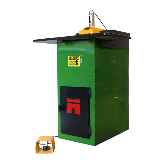
Summary of Contents for CASTLE TSM-22
- Page 1 CASTLE, INC. Diagnostic Manual TSM-22 Pocket Hole Machine CASTLE INC PO BOX 750236 PETALUMA CA 94975 WWW.CASTLEUSA.COM...
-
Page 2: Table Of Contents
Table of Contents INTRODUCTION ..........................4 ......................5 OW TO ANUAL DRY CYCLE TESTING 21.95 ....................6 ..........................6 URPOSE TSM-22........................6 Option #2 Dry Test TSM-22 With Work Top Open..............8 DEFINITIONS ..........................11 DIAGNOSTIC DESCRIPTIONS....................13 ........................13 LAMP PERATION ........................15 OUTER PERATION ........................17 RILL PERATION ............18... - Page 3 ACHINE PERATORS APPENDIX B – WIRING DIAGRAM 21.84 ................69 APPENDIX C – CONTROL BOX WORKS 21.93 ..............70 APPENDIX D – SOLENOID, PNEUMATIC DIAGRAM 21.94 ..........72 APPENDIX E – INDEX ......................73 Castle Inc TSM-22 Diagnostic Manual V1 Page 3 of 74...
-
Page 4: Introduction
1 Introduction Thank you for making the Castle TSM-22 Screw Pocket Machine a vital part of your shop. The TSM-22 is designed for use on a wide variety of materials including hardwoods, softwoods, melamine, particleboard and MDF. This manual is intended for anyone working with, or performing maintenance or service on the TSM-22. -
Page 5: How To Use This Manual
. Check clamp Solenoid for function or blockage 21.11 12-13 Note: If you are unsure of your observations or if the fault behaviour seems irregular you should “Dry Cycle” test the machine. See Procedure 21.95, page 6. TSM-22 Diagnostic Manual V1 Page 5 of 74 Castle Inc... -
Page 6: Dry Cycle Testing 21.95
2 Dry Cycle Testing 21.95 2.1 Purpose Dry Cycle testing allows observation of the TSM-22’s mechanical, electrical, and pneumatic functions without routing pockets or drilling holes. Caution: Careful observation is essential when troubleshooting or seeking Technical Support 2.2 Dry Test TSM-22 Locate the ON/OFF switches on the Router and Drill and turn them both off 2. - Page 7 Procedures 21.83, 21.20 and 21.60 Note: For comprehensive diagnostic descriptions and procedures refer to Section IV. After testing is complete, turn the MAIN Power Switch OFF and switch both motors back ON TSM-22 Diagnostic Manual V1 Page 7 of 74 Castle Inc...
-
Page 8: Option #2 Dry Test Tsm-22 With Work Top Open
2.3 Option #2 Dry Test TSM-22 With Work Top Open 1. Connect air and power to the machine. Turn the machine’s MAIN Power Switch ON. 2. Lift the work top of the machine. 3. Depress one of the Safety Buttons with a piece of scrap wood. Position yourself in front of the machine. - Page 9 Note: If a dry cycle is preformed to confirm function of the switches and the router bit or the drill bit stays extended, verify that the carriage plate is not hitting the front of the switch/magnet. The carriage plate should land in between the switch and the magnet. TSM-22 Diagnostic Manual V1 Page 9 of 74 Castle Inc...
- Page 10 Procedures 21.92, 21.90 and 21.32 Note: For comprehensive diagnostic descriptions and procedures refer to Section IV. After testing is complete, turn the MAIN Power Switch OFF, then lower and secure the work top. TSM-22 Diagnostic Manual V1 Page 10 of 74 Castle Inc...
-
Page 11: Definitions
Controls the speed at which the Pocket Router moves through the Valve material when cutting the Pocket. Note: Should be adjusted AFTER the main operational speed of the machine has been set with the Air Pressure Regulator. Castle Inc TSM-22 Diagnostic Manual V1 Page 11 of 74... - Page 12 Safety Switch Normally CLOSED (NC) switches Router Stop Switch Drill Stop Switch The distance between the deepest part of the pocket and the edge of the material. TSM-22 Diagnostic Manual V1 Page 12 of 74 Castle Inc...
-
Page 13: Diagnostic Descriptions
□ Check Clamp Solenoid for blockage……………………..….. 21.10 Clamp doesn’t come down, Machine Does NOT Rout or Drill: □ Check Foot Switch………………………........… 57 21.80 □ Check Safety Switch (Stock Sense).……………………………… 21.82 TSM-22 Diagnostic Manual V1 Page 13 of 74 Castle Inc... - Page 14 □ □ Check Bar Spring position........………………….. 21.42 Clamp doesn’t release…Machine Routs but Router DOES NOT retract, DOES NOT Drill: □ Router Stop switch…………………………………………………... 21.22 □ □ Check Bar Spring position........…………………….. 45 21.42 Castle Inc TSM-22 Diagnostic Manual V1 Page 14 of 74...
-
Page 15: Router Operation
21.50 □ ..…………………………………..... 21.60 □ ……………………………………. ……………………………………. 21.65 □ Bar Spring Position......………………..... 21.42 Router advances too aggressively: □ Adjust internal Air Pressure………………………………………… 21.90 □ Adjust the Router Feed Rate……………………………………….. 21.32 Castle Inc TSM-22 Diagnostic Manual V1 Page 15 of 74... - Page 16 Check Router Feed Rate (may be turned all the way down)…..21.32 □ Check Router Solenoid for function or blockage……………..….…. 21.31 □ Drive Cylinder for leaks……………………………..…….. 21.60 □ for Blockage in Drill Solenoid Exhaust Muffler..…………….. 21.65 Castle Inc TSM-22 Diagnostic Manual V1 Page 16 of 74...
-
Page 17: Drill Operation
□ Drill bit dull, Change drill bit............21.83 Drill bit separating from the shank: □ Adjust air pressure, Machine cycling too slowly………………….. 21.90 □ Bit mounted too deep into collet……………………………………. 21.41 Castle Inc TSM-22 Diagnostic Manual V1 Page 17 of 74... -
Page 18: Overall Machine Operation And Pocket Adjustment
□ Check for other air driven machines on the same line…………... 21.90 for Blockage in Drill Solenoid Exhaust Muffler..…...…….. □ 21.65 □ for Blockage in Router Solenoid Exhaust Muffler ……..21.65 Castle Inc TSM-22 Diagnostic Manual V1 Page 18 of 74... - Page 19 □ Adjust Pilot Hole alignment…………………………………………. 21.72 □ Check Drill motor mounting………………………………………… 21.40 Pocket too close or too far from the edge of the stock, WEB adjustment: □ Adjust Web with Router Stop Plate………………………………... 21.21 TSM-22 Diagnostic Manual V1 Page 19 of 74 Castle Inc...
-
Page 20: Procedures
1. Remove the air line out fitting and the exhaust muffler and press the override button for several seconds. Air should flow through the solenoid. Reassemble and cut a test pocket. Fig 4 TSM-22 Diagnostic Manual V1 Page 20 of 74 Castle Inc... -
Page 21: Clamp Foot Pad Or Cylinder Replacement
¾” wrench. Continue holding the shaft stationary with the ½” wrench and use large slip-joint pliers to turn the Clamp Foot and break it free of thread lock com- pound. See Fig 3. Jamb Nut Clamp Foot Foot Pad Fig 3 TSM-22 Diagnostic Manual V1 Page 21 of 74 Castle Inc... -
Page 22: Unclogging The Clamp Solenoid 21.10
Note: To remove the air line from the clamp cylinder, push in the plastic or metal rim of the fitting and pull the air line out. To re-install, push the air line in until it meets resistance and then push in another 1/2'”. Fig 5 Castle Inc TSM-22 Diagnostic Manual V1 Page 22 of 74... - Page 23 4. Lower and secure the work top, then reconnect power. Cut a test pocket. Note: If this procedure does not correct the problem, the Clamp Solenoid will need to be replaced. Refer to Procedure 21.91, “Replacing Solenoids” Castle Inc TSM-22 Diagnostic Manual V1 Page 23 of 74...
-
Page 24: Clamp Solenoid Check 21.11
3. If the clamp does not extend, lift the work top of the machine Locate the manual overide button on the clamp solenoid. See FIG 6 and Fig 6a FIG. 6 Castle Inc TSM-22 Diagnostic Manual V1 Page 24 of 74... - Page 25 If the clamp cylinder does not extend, then the Clamp Solenoid may be stuck closed or clogged. If the Clamp Solenoid is stuck open/closed or clogged, Perform procedure 21.10, Unclogging the Clamp Solenoid. Castle Inc TSM-22 Diagnostic Manual V1 Page 25 of 74...
-
Page 26: Clamp Cylinder Check 21.12
5. If both clamp actions are smooth and quick the Clamp Cylinder is operating properly. Continue troubleshooting the Clamp Cylinder Air Line, the Exhaust Muffler on the Clamp Solenoid and the Clamp Solenoid. See Fig 8. Castle Inc TSM-22 Diagnostic Manual V1 Page 26 of 74... -
Page 27: Clamp Exhaust Check 21.13
5.6.1 TROUBLESHOOTING STEPS: Lift the work top on the machine. The Exhaust muffler is the brass fitting located next to the air inlet on the clamp solenoid. See Fig 9. Castle Inc TSM-22 Diagnostic Manual V1 Page 27 of 74... - Page 28 3. The exhaust muffler can be temporarily removed to test the clamp response. If the clamp returns at normal pace without the exhaust muffler then the exhaust muffler is obstructed and needs replaced. Castle Inc TSM-22 Diagnostic Manual V1 Page 28 of 74...
-
Page 29: Router Motor Operation 21.20
Remove the plug from the plate b first lifting the plug then lug can now be removed from the retention plate. See b turning degrees. Fig 10a. Fig 10 Fig 10a Castle Inc TSM-22 Diagnostic Manual V1 Page 29 of 74... - Page 30 Reinstall the plug with the retention plate and 3 screws in reverse order. Care must be taken to position the plug correctly. The wider electric prong on the plug should be closest to the center of the machine. See FIG 12. Fig 12 Castle Inc TSM-22 Diagnostic Manual V1 Page 30 of 74...
- Page 31 3. Warranty replacement and parts purchases can be handled by your nearest Bosch dealer/service center, or Castle. 4. The Router Motor has two electrical brushes that should be periodically replaced. See Fig 13. Fig 13 Castle Inc TSM-22 Diagnostic Manual V1 Page 31 of 74...
-
Page 32: Adjusting The Web , Router Stop Plate 21.21
Web. 4. Secure the lock nut after making any adjustments. Castle Inc TSM-22 Diagnostic Manual V1 Page 32 of 74... -
Page 33: Router Stop Switch (Nc) 21.22
2. The Router Stop Switch and Magnet are attached to the front side of the Router Stop Plate, which is located just to the right of the control box. See Fig 15. Fig 15 Castle Inc TSM-22 Diagnostic Manual V1 Page 33 of 74... - Page 34 Note: If a dry cycle is preformed to confirm function of the switch and the router bit stays extended, verify that the carriage plate is not hitting the front of the switch/magnet. The carriage plate should land in between the switch and the magnet. Castle Inc TSM-22 Diagnostic Manual V1 Page 34 of 74...
-
Page 35: Unclogging The Router Solenoid 21.30
Note: If this procedure does not correct the problem, the Router Solenoid will need to be replaced. Refer to Procedure 21.91, “Replacing Solenoids”. Rule of Thumb: Router feed speed should be as fast as possible while still maintaining smooth, clean, straight pockets. Castle Inc TSM-22 Diagnostic Manual V1 Page 35 of 74... -
Page 36: Router Check Solenoid 21.31
3. If the router does not extend, lift the work top of the machine Locate the manual overide button on the router solenoid. See FIG 17 and Fig 17a FIG. 17 Castle Inc TSM-22 Diagnostic Manual V1 Page 36 of 74... -
Page 37: Router Feed Rate Adjustment 21.32
Rule of Thumb: Router feed speed should be as fast as possible while still maintaining smooth, clean, straight pockets. The harder the material, the slower the feed rate of the Router. Castle Inc TSM-22 Diagnostic Manual V1 Page 37 of 74... -
Page 38: Drill Motor Operation 21.40
Feed Rate valve up slightly (counter clockwise). If the router moves slowly then the router feed valve should be OK. If the router comes up extremely fast, replace the router feed rate valve. Castle Inc TSM-22 Diagnostic Manual V1 Page 38 of 74... - Page 39 TIGHTENING THE DRILL MOTOR: 1. Lift the work top of the machine. 2. The Drill Motor is mounted on top of the red Motor Carriage. See Fig 19. Fig 19 Castle Inc TSM-22 Diagnostic Manual V1 Page 39 of 74...
- Page 40 Please note that the spindle lock of the Drill Motor will be pointed up. See Fig 19a. Hold the Drill Motor in position as you tighten the two lock nuts on the U-Bolt. Fig 19a Castle Inc TSM-22 Diagnostic Manual V1 Page 40 of 74...
- Page 41 Please note that the spindle lock of the Drill Motor will be pointed up. See Fig 21. Hold the Drill Motor in position as you tighten the two lock nuts on the U-Bolt. Castle Inc TSM-22 Diagnostic Manual V1 Page 41 of 74...
- Page 42 Reach through the front access door and manually rock the Motor Carriage toward the front of the machine to make sure that the Drill Bit cleanly fits through the hole on the face plate. Castle Inc TSM-22 Diagnostic Manual V1 Page 42 of 74...
- Page 43 4. The Drill Motor has two electrical brushes that should be periodically replaced. See Fig 23. Fig 23 Castle Inc TSM-22 Diagnostic Manual V1 Page 43 of 74...
-
Page 44: Drill Settings And Bit Depth 21.41
5.14 Drill Settings and Bit Depth 21.41 The TSM-22 is designed to handle many types and thicknesses of material. Depending on screw type and length, and the thickness of the material, the drill collet setting may need to be adjusted. If the drill bit appears blackened or burned it is spending too much time boring the Pilot Hole and may overheat and loosen in its shank. -
Page 45: Drill Single Coil Bar Spring 21.42
2. The 2 carriage bolts on the left anchor the Bar Spring. Loose booth of the carriage bolt nuts and slid the bar up and to the right to remove. See Fig 25. Fig 25 Castle Inc TSM-22 Diagnostic Manual V1 Page 45 of 74... - Page 46 Reposition the bar spring to the front of the carriage bolt (see Fig 26) to correct. Castle Inc TSM-22 Diagnostic Manual V1 Page 46 of 74...
-
Page 47: Drill Stop Switch (Nc) 21.43
2. The Drill Stop Switch and magnet are located inside the machine on the back side of the Face Plate, slightly to the right of the Pilot Drill Hole. See Fig 27. Fig 27 Castle Inc TSM-22 Diagnostic Manual V1 Page 47 of 74... - Page 48 Note: If a dry cycle is preformed to confirm function of the switch and the drill bit stays extended, verify that the carriage plate is not hitting the front of the switch/magnet. The carriage plate should land in between the switch and the magnet. Castle Inc TSM-22 Diagnostic Manual V1 Page 48 of 74...
-
Page 49: Unclogging The Drill Solenoid 21.50
4. Lower and secure the work top, then and reconnect power. Cut a test pocket. Note: If this procedure does not correct the problem, the Drill Solenoid will need to be replaced. Refer to Procedure 21.91, “Replacing Solenoids” Castle Inc TSM-22 Diagnostic Manual V1 Page 49 of 74... -
Page 50: Drill Solenoid Check 21.51
3. If the drill does not extend, lift the work top of the machine Locate the manual overide button on the drill solenoid. See FIG 29 and Fig 29a FIG. 29 Castle Inc TSM-22 Diagnostic Manual V1 Page 50 of 74... - Page 51 If the carriage does not tilt toward the front of the machine, then the Drill Solenoid may be stuck closed or clogged. If the Drill Solenoid is stuck open or clogged, Perform procedure 21.50, Unclogging the Drill Solenoid. Castle Inc TSM-22 Diagnostic Manual V1 Page 51 of 74...
-
Page 52: Drive Cylinder Check 21.60
Carriage will tilt toward the back of the machine and stop. 4. Listen for constant hissing and feel for leaking air at the exhaust ports of the Router Solenoid and the Drill Solenoid. See Fig 30. Fig 30 Castle Inc TSM-22 Diagnostic Manual V1 Page 52 of 74... - Page 53 Place a Screw driver or piece of metal in between the Router Stop Switch and the Router Stop Magnet. This will trigger the carriage to come forward and stop. See Fig 31. Fig 31 Castle Inc TSM-22 Diagnostic Manual V1 Page 53 of 74...
- Page 54 13. Cycle the machine a few more times (start back at step 9) to see if the situation can be repeated. 14. If the stalled Drive Cylinder consistently leaks air, the cylinder must be replaced. Castle Inc TSM-22 Diagnostic Manual V1 Page 54 of 74...
-
Page 55: Exhaust Mufflers On Solenoid Valves
Mufflers as sawdust can be pulled back into solenoid valve and cause issues. 5.20.1 TESTING STEPS: 1. Lift the work top o the machine. Remove the exhaust mufflers from the Router and Drill Solenoids. See Fig 32. Fig 32 Castle Inc TSM-22 Diagnostic Manual V1 Page 55 of 74... - Page 56 4. Reconnect the air lines to the Drive Cylinder as shown Fig 32. Note: It is never recommended to run the machine without Exhaust Mufflers as sawdust can be pulled back into solenoid valve and cause issues. Castle Inc TSM-22 Diagnostic Manual V1 Page 56 of 74...
-
Page 57: Pilot Hole Alignment 21.72
The Foot Switch is located in the Foot Pedal. At rest, the Foot Switch is normally OPEN. It works in conjunction with the Safety Buttons/ Safety Switch. Closing the Foot Switch (while simultaneously closing the Safety Switch) starts the machine cycle. Castle Inc TSM-22 Diagnostic Manual V1 Page 57 of 74... - Page 58 Note: A quick way to test the foot switch is to test for continuity on terminals 3 and 4 of the control board pressing down on the foot pedal. ONLY PERFORM THIS OPERATION WITH THE UNIT UNPLUGGED. Castle Inc TSM-22 Diagnostic Manual V1 Page 58 of 74...
-
Page 59: Resetting The Machine 21.81
1. Disconnect power and air from the machine. Lift the work top of the machine. 2. The reed switch and magnet are mounted to the right of the control box See Fig 35. Castle Inc TSM-22 Diagnostic Manual V1 Page 59 of 74... - Page 60 OPEN, the distance between the switch and magnet may need to be de- creased by 1/16”. 6. If the switch will not change from OPEN to CLOSED when the Safety Blade is raised de- spite adjustment, replace the switch and the magnet. Castle Inc TSM-22 Diagnostic Manual V1 Page 60 of 74...
-
Page 61: Tooling Check And Replacement 21.83
3. Replace the bit. A Bit Gauge is provided to record your preferred Drill Bit Extension. Once a preferred setting is selected, mark or scribe your settings on the aluminum plate. ("D" Drill). See FIG 37. Castle Inc TSM-22 Diagnostic Manual V1 Page 61 of 74... - Page 62 Lower and secure the work top. Through the front door, manually rock the Motor Carriage toward the front of the machine and make sure that the Drill Bit cleanly fits through the hole on the face plate. Castle Inc TSM-22 Diagnostic Manual V1 Page 62 of 74...
-
Page 63: Air Pressure Regulator Setting 21.90
Note: It’s extremely important that a minimum 85 PSI be provided from your compressor. Operating pressure can be especially affected by other machines that share the same air line as your TSM-22. 5.26.1 TO RESET THE AIR PRESSURE REGULATOR: 1. -
Page 64: Replacing Solenoid Valves 21.91
Raise the work top of the machne. Label the three solenoids and remove the two hex nuts and lock washers that hold the solenoids together. See Fig 39. Fig 39 Castle Inc TSM-22 Diagnostic Manual V1 Page 64 of 74... - Page 65 Reassemble the solenoids in a stack and tighten the hex nuts and lock washers. Do not over tighten the hex nuts. 9. Reconnect air and then power to the machine. Castle Inc TSM-22 Diagnostic Manual V1 Page 65 of 74...
-
Page 66: Attaching Air Supply 21.92
5.28 Attaching Air Supply 21.92 An air supply with a MINIMUM of 85 PSI must be provided for proper operation of the TSM-22 Pocket Machine. 1. From the operator’s position the air inlet is the 1/4” NPT fitting located on the back side. -
Page 67: Appendix A - Machine Safety 21.80
Keep both hands on the work piece when initiating a Pocket Cycle on this machine. Before attempting adjustments, maintenance, or repair, STOP this machine and disconnect it from the compressed air supply and AC mains power. Wait for all motion Castle Inc TSM-22 Diagnostic Manual V1 Page 67 of 74... - Page 68 AC mains power. Always keep the area around the machine clean and uncluttered. Poor housekeeping could result in slips, falls or other injuries. Castle Inc TSM-22 Diagnostic Manual V1 Page 68 of 74...
-
Page 69: Appendix B - Wiring Diagram
Drill Solenoid Valve 15/16 Router Solenoid Valve 13/14 Clamp Solenoid Valve 11/12 Drill Stop Switch (NC-Normally Closed) 9/10 Router Stop Switch (NC-Normally Closed) Wood Sensor Switch (NO-Normally Open) Foot Switch (NO-Normally Open) Castle Inc TSM-22 Diagnostic Manual V1 Page 69 of 74... -
Page 70: Appendix C - Control Box Works 21.93
8 Appendix C – Machine Works 21.93 Fig 41 Fig 42 Castle Inc TSM-22 Diagnostic Manual V1 Page 70 of 74... - Page 71 Fig 43 Castle Inc TSM-22 Diagnostic Manual V1 Page 71 of 74...
-
Page 72: Appendix D - Solenoid, Pneumatic Diagram 21.94
9 Appendix D – Solenoid, Pneumatic Diagram 21.94 Castle Inc TSM-22 Diagnostic Manual V1 Page 72 of 74... -
Page 73: Appendix E - Index
Drive Cylinder , Check ……………………………………………………..21.60 Exhaust Muffler Check ................21.65 Dry Cycle Testing ……………………………………………………………..21.95 Foot Switch , normally open (NO)………………………………………………. 21.80 Machine Safety, Appendix A …………………………………………………... 21.96 Pilot Hole , Alignment…………………………………………………………….. 21.72 Castle Inc TSM-22 Diagnostic Manual V1 Page 73 of 74... - Page 74 21.94 Solenoid Valves, Replacing…………………………………………………….. 21.91 Solenoid Valves, Manual Override..………………………………………….. 21.01 Tooling , Check & Replacement………………………………………………… 21.83 Web adjustment with the Router Stop Plate…………………………………… 21.21 Wiring Diagram, Appendix B ………………………………………………….. 21.84 Castle Inc TSM-22 Diagnostic Manual V1 Page 74 of 74...
Need help?
Do you have a question about the TSM-22 and is the answer not in the manual?
Questions and answers