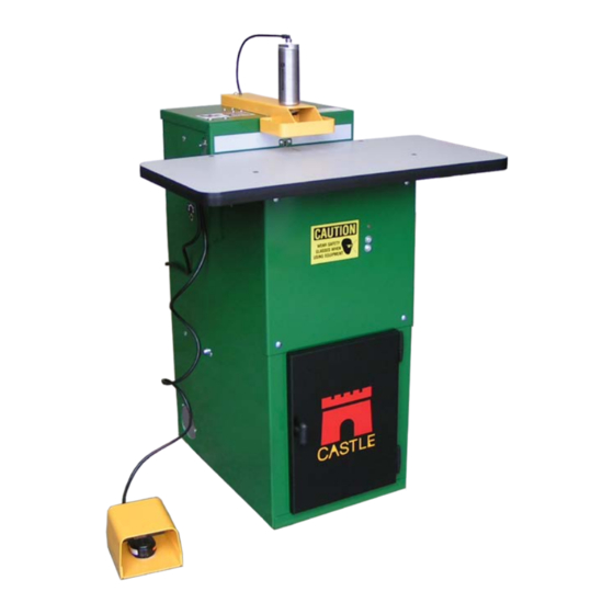
CASTLE TSM-21 Diagnostic Manual
Screw pocket machine
Hide thumbs
Also See for TSM-21:
- Installation instructions manual (25 pages) ,
- Diagnostic manual (67 pages)
Table of Contents
Advertisement
Advertisement
Table of Contents

Subscribe to Our Youtube Channel
Related Manuals for CASTLE TSM-21


Summary of Contents for CASTLE TSM-21
- Page 1 CASTLE INC Diagnostic Manual TSM-21...
-
Page 2: Table Of Contents
21.42 ................36 RILL INGLE PRING 5.16 (NC) 21.43 ..................37 RILL WITCH 5.17 21.50 ................38 NCLOGGING THE RILL OLENOID 5.18 21.51 ..................40 RILL OLENOID HECK 5.19 21.60 ..................41 RIVE YLINDER HECK Castle Inc TSM-21 Diagnostic Manual v2 Page 2 of 63... - Page 3 ...............58 APPENDIX D – SOLENOID, PNEUMATIC DIAGRAM 21.94 ............59 APPENDIX E – CONTROL BOX WORKS 21.93 ..............60 APPENDIX F – SOLENOID, PNEUMATIC DIAGRAM 21.94 ..........61 APPENDIX G – INDEX ......................62 Castle Inc TSM-21 Diagnostic Manual v2 Page 3 of 63...
-
Page 4: Introduction
1 Introduction Thank you for making the Castle TSM-21 Screw Pocket Machine a vital part of your shop. The TSM-21 is designed for use on a wide variety of materials including hardwoods, softwoods, melamine, particleboard and MDF. This manual is intended for anyone working with, or performing maintenance or service on the TSM-21. -
Page 5: How To Use This Manual
□ Check clamp Solenoid for function or blockage 21.11 12-13 Note: If you are unsure of your observations or if the fault behaviour seems irregular you should “Dry Cycle” test the machine. See Procedure 21.95, page 4. Castle Inc TSM-21 Diagnostic Manual v2 Page 5 of 63... -
Page 6: Dry Cycle Testing 21.95
2 Dry Cycle Testing 21.95 2.1 Purpose Dry Cycle testing allows observation of the TSM-21’s mechanical, electrical, and pneumatic functions without routing pockets or drilling holes. Careful observation is essential when troubleshooting or seeking Technical Caution: Support. 2.2 Dry Test TSM-21 1. - Page 7 Note: For comprehensive diagnostic descriptions and procedures refer to Section IV. After testing is complete, turn the MAIN Power Switch OFF and switch both motors back ON or plug them both back into the Control Box outlet. Castle Inc TSM-21 Diagnostic Manual v2 Page 7 of 63...
-
Page 8: Definitions
Controls the speed at which the Pocket Router moves through the Router Feed Rate material when cutting the Pocket. Valve Note: Should be adjusted AFTER the main operational speed of the machine has been set with the Air Pressure Regulator. Castle Inc TSM-21 Diagnostic Manual v2 Page 8 of 63... - Page 9 Safety Switch Normally CLOSED (NC) switches Router Stop Switch Drill Stop Switch The distance between the deepest part of the pocket and the edge of the material. Castle Inc TSM-21 Diagnostic Manual v2 Page 9 of 63...
-
Page 10: Diagnostic Descriptions
□ Router Feed Speed too fast, adjust Router Feed Rate………….. 21.32 31-32 □ Check Tooling, may be dull………………………………………… 21.83 49-50 □ Check Pilot Valve for function or blockage……………………….. 21.14 22-24 (up to machine sn: 61076 Only) Castle Inc TSM-21 Diagnostic Manual v2 Page 10 of 63... - Page 11 (up to machine sn: 61076 Only) □ Check Drill Solenoid for function or blockage…………………….. 21.51 40-41 Clamp doesn’t release…Machine Routs but Router DOES NOT retract, DOES NOT Drill: □ Router Stop switch…………………………………………………... 21.22 27-29 Castle Inc TSM-21 Diagnostic Manual v2 Page 11 of 63...
-
Page 12: Router Operation
Router cuts pocket, Drill doesn’t come out and Clamp doesn’t release: □ Check Drill Solenoid for function or blockage…………………….. 21.50 38-39 Router advances too aggressively: □ Adjust internal Air Pressure………………………………………… 21.90 51-52 □ Adjust the Router Feed Rate……………………………………….. 21.32 31-32 Castle Inc TSM-21 Diagnostic Manual v2 Page 12 of 63... -
Page 13: Drill Operation
□ Bit mounted too deep into collet……………………………………. 21.41 34-35 Drill bit separating from the shank: □ Adjust air pressure, Machine cycling too slowly………………….. 21.90 51-52 □ Bit mounted too deep into collet……………………………………. 21.41 34-35 Castle Inc TSM-21 Diagnostic Manual v2 Page 13 of 63... -
Page 14: Overall Machine Operation And Pocket Adjustment
Note: A normal cycle is approximately 2 seconds □ Adjust Air Pressure Regulator……………………………………… 21.90 51-52 □ Check Drive cylinder for air leak…………………………………… 21.60 41-42 □ Check for other air driven machines on the same line…………... 21.90 51-52 Castle Inc TSM-21 Diagnostic Manual v2 Page 14 of 63... - Page 15 □ Check Drill motor mounting………………………………………… 21.40 33-34 Pocket too close or too far from the edge of the stock, WEB adjustment: □ Adjust Web with Router Stop Plate………………………………... 21.21 26-27 Castle Inc TSM-21 Diagnostic Manual v2 Page 15 of 63...
-
Page 16: Procedures
¾” wrench. Continue holding the shaft stationary with the ½” wrench and use large slip-joint pliers to turn the Clamp Foot and break it free of thread lock com- pound. See Fig 1. Jamb Nut Clamp Foot Foot Pad Fig 1 Castle Inc TSM-21 Diagnostic Manual v2 Page 16 of 63... -
Page 17: Unclogging The Clamp Solenoid
Use the “Air In” line to clean out both open ports on the Clamp solenoid. 3. Disconnect the air supply and reinsert the “Air In” line back into the “Air In” port of the solenoid. 4. Un-plug or turn off both routers. Castle Inc TSM-21 Diagnostic Manual v2 Page 17 of 63... -
Page 18: Clamp Solenoid Check
SN: 61076 and above. 5.3.1 Troubleshooting Steps: 1. Disconnect air supply from the machine. 2. Swap the "Air Out" lines between the Clamp Solenoid and the Router Solenoid. See Fig Castle Inc TSM-21 Diagnostic Manual v2 Page 18 of 63... -
Page 19: Clamp Cylinder Check
¼” air line from the Clamp Cylinder to the Pilot Valve (up to machine SN: 61076) or from the Clamp Cylinder to the Clamp Solenoid (machine SN: 61076 and up). Castle Inc TSM-21 Diagnostic Manual v2 Page 19 of 63... - Page 20 5. If both clamp actions are smooth and quick the Clamp Cylinder is operating properly. Continue troubleshooting the Clamp Cylinder Air Line, the Pilot Valve (on Mead solenoid machines) and the Clamp Solenoid. See Fig 5. Castle Inc TSM-21 Diagnostic Manual v2 Page 20 of 63...
-
Page 21: Pilot Valve, Clamp Exhaust Check
5.5.1 TROUBLESHOOTING STEPS: 1. Open the rear door on the machine. The Exhaust port is the small, white plastic barb to the left of the regulator knob. See Fig 6. Castle Inc TSM-21 Diagnostic Manual v2 Page 21 of 63... -
Page 22: Pilot Valve Check And Replacement
Clamp regardless of the Pressure regulator setting. 5.6.1 TROUBLESHOOTING STEPS: 1. Disconnect the “Air Out” line from the Clamp Solenoid (this hose controls the Pilot Valve). See Fig 7. Castle Inc TSM-21 Diagnostic Manual v2 Page 22 of 63... - Page 23 4. Remove the two black hoses connected to the Pilot Valve. 5. Remove the Pilot Valve from the brass fittings. 6. Transfer the three white plastic fittings to the corresponding positions on the new Pilot valve. Castle Inc TSM-21 Diagnostic Manual v2 Page 23 of 63...
-
Page 24: Router Motor Operation
2. Open the rear door and locate the Drill Motor. Just to the right is a T-Knob that tightens a large U-Bolt holding the Router Motor in place. See Fig 8. Castle Inc TSM-21 Diagnostic Manual v2 Page 24 of 63... - Page 25 2. The Router motor is warranted for one year from the purchase of the machine. 3. Warranty replacement and parts purchases can be handled by your nearest Porter Cable dealer/service center, or Castle. Castle Inc TSM-21 Diagnostic Manual v2 Page 25 of 63...
-
Page 26: Adjusting The Web, Router Stop Plate
1. The Router Stop Plate is a black bracket found on the right side of the yellow Clamp Guard. 2. It is held in place by a ¼” lock nut. See Fig 10. Castle Inc TSM-21 Diagnostic Manual v2 Page 26 of 63... -
Page 27: Router Stop Switch (Nc)
If the switch fails, or the magnetic field weakens or becomes misaligned, the machine will not sense the end of the rout cycle properly and the router may stay forward in the pocket causing Castle Inc TSM-21 Diagnostic Manual v2 Page 27 of 63... - Page 28 7. If the switch measures OPEN while the Motor Carriage is in neutral position, adjust the magnet 1/16” closer to the switch and repeat the test. Make additional adjustments closer until the switch measures CLOSED. Castle Inc TSM-21 Diagnostic Manual v2 Page 28 of 63...
-
Page 29: Unclogging The Router Solenoid
“Air Out” port of the valve. Gently open the Router Feed Rate valve (lo- cated on the left hand side of the machine below the air inlet) fully counter clockwise. Castle Inc TSM-21 Diagnostic Manual v2 Page 29 of 63... -
Page 30: Router Check Solenoid
SN: 61076 and above. 5.11.1 TROUBLESHOOTING STEPS: 1. Detach the air supply from the machine. 2. Swap the "Air Out" lines between the Router Solenoid and the Drill Solenoid. See Fig 13. Castle Inc TSM-21 Diagnostic Manual v2 Page 30 of 63... -
Page 31: Router Feed Rate Adjustment
As a rule of thumb – the harder the material, the slower the feed rate of the Router. Note: If the Pressure Regulator has been adjusted, readjust the Router Feed Rate (if necessary) AFTER the Pressure Regulator setting has been finalized. Castle Inc TSM-21 Diagnostic Manual v2 Page 31 of 63... - Page 32 7. Tighten the Jamb Nut after adjustments are finalized. Note: If the Router comes up with the Feed rate knob turned fully clockwise, the Feed rate valve should be replaced. Castle Inc TSM-21 Diagnostic Manual v2 Page 32 of 63...
-
Page 33: Drill Motor Operation
2. The Drill Motor is mounted on top of the yellow Motor Carriage. See Fig 15. Drill Motor Drill T-Knob Fig 15 3. Locate the Drill T-Knob on left side of the Motor Carriage. 4. Gently rock the Drill Motor as you tighten the T-Knob Castle Inc TSM-21 Diagnostic Manual v2 Page 33 of 63... -
Page 34: Drill Settings And Bit Depth
4. The Drill Motor has two electrical brushes that should be periodically replaced. Note: During assembly at Castle, the front housing of the drill motor is rotated 90 degrees to orient the power cord straight down relative to the T-Knob bolt hole. Replacement motors obtained through sources other than Castle may need to have the front housing rotated similarly. - Page 35 “D” for Drill and “R” for Router. 2. The plate has two sides that can be used settings for different processes in the shop. Castle Inc TSM-21 Diagnostic Manual v2 Page 35 of 63...
-
Page 36: Drill Single Coil Bar Spring
See Fig 17. Bar Spring Motor Carriage Carriage Bolt Fig 17 5. Make sure the Bar Spring is on the front side of the 3” carriage bolt and tighten the nuts. Castle Inc TSM-21 Diagnostic Manual v2 Page 36 of 63... -
Page 37: Drill Stop Switch (Nc)
2. The Drill Stop Switch and magnet are located inside the machine on the back side of the Face Plate, slightly to the left of the Pilot Drill Hole. See Fig 18. Drill Stop Switch Motor Carriage Drill Stop Magnet Fig 18 Castle Inc TSM-21 Diagnostic Manual v2 Page 37 of 63... -
Page 38: Unclogging The Drill Solenoid
9. If the switch needs to be replaced the laminate strip on the front of the machine may need to be removed to access the switch retaining screws. Pry the laminate free from the case with a sharpened putty knife. Contact Castle for a replacement laminate strip. 5.17 Unclogging the Drill Solenoid 21.50... - Page 39 8. Turn the routers back on and cut a test pocket. Note: If this procedure does not correct the problem, the Drill Solenoid will need to be re- placed. Refer to Procedure 21.91, “Replacing Solenoids” page 47-48 Castle Inc TSM-21 Diagnostic Manual v2 Page 39 of 63...
-
Page 40: Drill Solenoid Check
2. Swap the "Air Out" lines between the Drill Solenoid and the Router Solenoid. See Fig 20. Clamp Exhaust Pilot Valve, up to sn:61076 Clamp Solenoid Router Solenoid Drill Solenoid Regulator Knob Air OUT lines Air IN lines Router Feed Rate knob Fig 20 Castle Inc TSM-21 Diagnostic Manual v2 Page 40 of 63... -
Page 41: Drive Cylinder Check
4. Listen for constant hissing and feel for leaking air at the open barbs on the SQE valves (or at the exhaust ports of the Rout Solenoid and the Drill Solenoid). See Fig 21. Castle Inc TSM-21 Diagnostic Manual v2 Page 41 of 63... - Page 42 12. Cycle the machine a few more times to see if the situation can be repeated. 13. If the stalled Drive Cylinder consistently leaks air, the cylinder must be replaced. Castle Inc TSM-21 Diagnostic Manual v2 Page 42 of 63...
- Page 43 Drive Cylinder SQE valves. See Fig 23. “Push In” rim while pulling out air line Drill Solenoid Drill Solenoid Air IN Line Air OUT Line Fig 22 Castle Inc TSM-21 Diagnostic Manual v2 Page 43 of 63...
- Page 44 11. Reconnect the air lines to the Drive Cylinder as shown Fig 23. Drive Cylinder Router SQE Valve Drill SQE Valve Drill Solenoid line Router Solenoid line Fig 23 12. Turn the routers back on and cut a test pocket. Castle Inc TSM-21 Diagnostic Manual v2 Page 44 of 63...
-
Page 45: Perators
The Foot Switch is located in the Foot Pedal. At rest, the Foot Switch is normally OPEN. It works in conjunction with the Safety Buttons/ Safety Switch. Closing the Foot Switch (while simultaneously closing the Safety Switch) starts the machine cycle. Castle Inc TSM-21 Diagnostic Manual v2 Page 45 of 63... - Page 46 OPEN. 7. If the switch fails this test it must be replaced. Remove the two remaining Phillips screws through the switch to remove it from the Foot Pedal. Castle Inc TSM-21 Diagnostic Manual v2 Page 46 of 63...
- Page 47 1. Disconnect power and air from the machine. 2. The reed switch and magnet are mounted on the case top to the right of the Drill Motor. See Fig 26. Castle Inc TSM-21 Diagnostic Manual v2 Page 47 of 63...
- Page 48 OPEN, the distance between the switch and magnet may need to be de- creased by 1/16”. 6. If the switch will not change from OPEN to CLOSED when the Safety Blade is raised de- spite adjustment, replace the switch and the magnet. Castle Inc TSM-21 Diagnostic Manual v2 Page 48 of 63...
- Page 49 (“R” Router) See Fig 28. 6. When re-installing, make sure the motor face is pushed up to seat flush with the tabs on the yellow carriage (if unsure, remove table top to confirm location). Castle Inc TSM-21 Diagnostic Manual v2 Page 49 of 63...
- Page 50 8. Tighten the Drill T-Knob onto the mounting bolt. 9. Manually rock the Motor Carriage toward the front of the machine and make sure that the Drill Bit cleanly fits through the hole on the face plate. Castle Inc TSM-21 Diagnostic Manual v2 Page 50 of 63...
- Page 51 Note: It’s extremely important that a minimum 85 PSI be provided from your compressor. Operating pressure can be especially affected by other machines that share the same air line as your TSM-21. 5.26.1 TO RESET THE AIR PRESSURE REGULATOR: 1.
- Page 52 3. Remove the two carriage bolts that hold the Control Box to the machine and pull the box partially out the rear door. See Fig 30. Carriage Bolts retaining the Control Box Fig 30 Castle Inc TSM-21 Diagnostic Manual v2 Page 52 of 63...
- Page 53 Note: For SN: 61076 and above, install the pneumatic fittings with a 7/16” wrench: Port #1 = Air IN, Port #2 = Air OUT, Port #3 = Exhaust muffler, then reconnect the air lines. Castle Inc TSM-21 Diagnostic Manual v2 Page 53 of 63...
- Page 54 5.28 Attaching Air Supply 21.92 An air supply with a MINIMUM of 80 PSI must be provided for proper operation of the TSM-21 Pocket Machine. 1. From the operator’s position the air inlet is the 1/4” NPT fitting located on the left side.
- Page 55 Keep both hands on the work piece when initiating a Pocket Cycle on this machine. Before attempting adjustments, maintenance, or repair, STOP this machine and disconnect it from the compressed air supply and AC mains power. Wait for all motion Castle Inc TSM-21 Diagnostic Manual v2 Page 55 of 63...
- Page 56 AC mains power. Always keep the area around the machine clean and uncluttered. Poor housekeeping could result in slips, falls or other injuries. Castle Inc TSM-21 Diagnostic Manual v2 Page 56 of 63...
- Page 57 Drill Solenoid Valve 15/16 Router Solenoid Valve 13/14 Clamp Solenoid Valve 11/12 Drill Stop Switch (NC-Normally Closed) 9/10 Router Stop Switch (NC-Normally Closed) Wood Sensor Switch (NO-Normally Open) Foot Switch (NO-Normally Open) Castle Inc TSM-21 Diagnostic Manual v2 Page 57 of 63...
- Page 58 Note: Up to SN: 61036 Clamp Exhaust Pilot Valve, up to SN: 61076 Clamp Solenoid Router Solenoid Drill Solenoid Regulator Knob Air OUT lines Air IN lines Router Feed Rate Knob Fig 32 Castle Inc TSM-21 Diagnostic Manual v2 Page 58 of 63...
- Page 59 9 Appendix D – Solenoid, Pneumatic Diagram 21.94 Note: Up to SN: 61036 Castle Inc TSM-21 Diagnostic Manual v2 Page 59 of 63...
- Page 60 Regulator Knob Air OUT lines Air IN lines Router Feed Rate Knob Fig 33 View from front of machine with work top removed Air IN Lines Exhaust Ports Fig 34 Castle Inc TSM-21 Diagnostic Manual v2 Page 60 of 63...
- Page 61 11 Appendix F – Solenoid, Pneumatic Diagram 21.94 Note: SN: 61076 and Above Castle Inc TSM-21 Diagnostic Manual v2 Page 61 of 63...
- Page 62 Foot Switch , normally open (NO)………………………………………………. 45-46 21.80 Machine Safety, Appendix A …………………………………………………... 55-56 21.96 Pilot Hole , Alignment…………………………………………………………….. 21.72 Pilot Valve , Exhaust Check……………………………………………………... 21-22 21.13 Pilot Valve , Check & Replacement…………………………………………….. 22-24 21.14 Castle Inc TSM-21 Diagnostic Manual v2 Page 62 of 63...
- Page 63 59 & 61 21.94 Solenoid Valves, Replacing…………………………………………………….. 52-54 21.91 Tooling , Check & Replacement………………………………………………… 49-50 21.83 Web adjustment with the Router Stop Plate…………………………………… 26-27 21.21 Wiring Diagram, Appendix B ………………………………………………….. 21.84 Castle Inc TSM-21 Diagnostic Manual v2 Page 63 of 63...
Need help?
Do you have a question about the TSM-21 and is the answer not in the manual?
Questions and answers
how to adjust the rauters to use a diferent size of screws