Sign In
Upload
Download
Table of Contents
Contents
Add to my manuals
Delete from my manuals
Share
URL of this page:
HTML Link:
Bookmark this page
Add
Manual will be automatically added to "My Manuals"
Print this page
×
Bookmark added
×
Added to my manuals
Manuals
Brands
Kruger Manuals
Fan
TDA Series
Installation and operating instructions manual
Kruger TDA Series Installation And Operating Instructions Manual
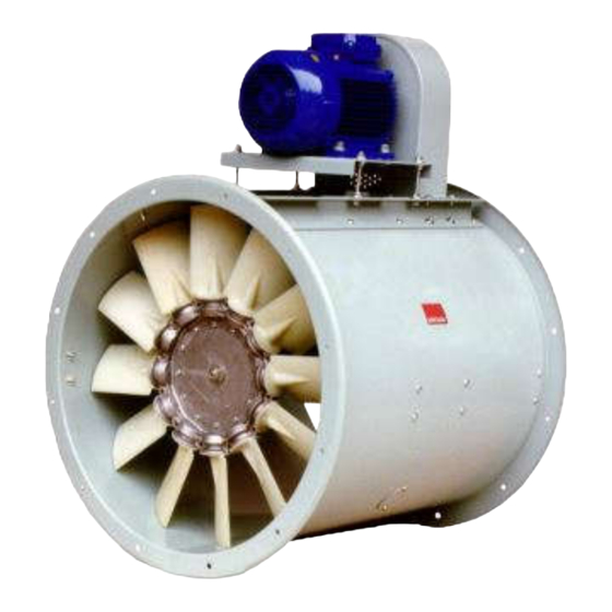
Axial fans
Hide thumbs
1
Table Of Contents
2
3
4
5
6
7
8
9
10
11
12
13
14
15
16
17
18
19
20
21
22
23
24
25
26
27
28
29
30
31
32
33
34
35
36
37
38
39
40
41
42
43
44
45
46
47
48
49
50
51
52
53
54
55
56
57
58
59
60
61
62
63
64
65
66
67
68
69
70
71
page
of
71
Go
/
71
Contents
Table of Contents
Bookmarks
Table of Contents
Table of Contents
Introduction
Purpose of this Manual
Safety Symbols Used in this Manual
Safety Symbols Used on Fans
General Information
Definitions, Basic Principles, Terminology Used and Correlated Documents
Construction Details of Axial Fans
Versions and Motor Positions
Flow Indications
Fan Name Plate
Fan Temperature Types
Description of Fan
Envisaged Use and Foreseeable Uses According to Experience, and Prohibited Uses
Life Cycle of Fan
Warnings and Main Safety Indications
Installation Instructions: General Information
Installation Type A: Instructions for Assembly, Installation and Connections
Installation Type B: Instructions for Assembly, Installation and Connections
Installation Type C: Instructions for Assembly, Installation and Connections
Installation Type D: Instructions for Assembly, Installation and Connections
Risks Involved in Foreseeable Incorrect Handling And/Or Abnormal Uses Based on Experience
Other Risks Related to Fans Pursuant to UNI en ISO 12499
Specific Risks with Fans During Installation
Specific Risks with Fans During Maintenance
Environmental Risks
Vibration Risks
Operating Speed Risks
Noise Emission Risks
General Information on Noise Emission Data
Transport, Movement and Storage
Lifting and Movement
General Warnings for Lifting Separate Fan Parts
Fan Lifting Instructions
Lifting Version 1 and 9 Axial Fans
Lifting Version 4 Axial Fans
Lifting Fans Packed in Crate
Storage
Installation
General Information
Minimum Installation Distances
Assembly of Axial Fans
Version 4 Axial Fans
Version 1 Axial Fans
Version 9 Axial Fans
Mounting Configuration
Installing and Adjusting Drive Belts and Final Checks
Vibration Isolator Installation
Blade Adjustment
Electrical Connections
Connection to Ducts
Checks to be Made before and after Starting
Preliminary Checks
Checks to be Made with Fan Fully Operating
Visual Checks on Protection Net
Checking and Cleaning Parts in Contact with Fluids
Visual Checks on Impeller and Casing
Dimensional Checks
Axial Fan Operating Malfunctions
Most Frequent Malfunctions
Maintenance
Bearing Lubrication
Adjusting Drive Belt Tension and Cleaning Belts
Checking and Cleaning Parts in Contact with Fluids
Dismantling and Reassembling Essential Components
Fan Impellers with Hub
Replacing Drive Belts
Assembling and Dismantling Pulleys
Assembling and Dismantling Drive Belts
Advertisement
Quick Links
1
Description of Fan
2
Installation Instructions: General Information
3
Installation Type A: Instructions for Assembly, Installation and Connections
4
Installation
Download this manual
Axial fans
Installation and Operating instructions
IGB010.E8 – December 2020
1 of 71
Table of
Contents
Previous
Page
Next
Page
1
2
3
4
5
Advertisement
Table of Contents
Need help?
Do you have a question about the TDA Series and is the answer not in the manual?
Ask a question
Questions and answers
Related Manuals for Kruger TDA Series
Fan Kruger TDA General Instructions Manual
Axial flow fan (10 pages)
Fan Kruger TDA General Instructions Manual
Axial flow fan (10 pages)
Fan Kruger TDC Series Installation And Operating Instructions Manual
Axial fans (71 pages)
Fan Kruger CSD Series General Instructions
Direct driven in-line fan (5 pages)
Fan Kruger APW II Series General Instructions
Propeller fan (4 pages)
Fan Kruger ADA Series General Instructions Manual
Centrifugal fan (13 pages)
Fan Kruger RDA Series General Instructions
Roof exhaust fan (5 pages)
Fan Kruger APL Series General Instructions
Propeller fan (4 pages)
Fan Kruger KCE 300 M Series General Instructions
(2 pages)
Fan Kruger KVS Series General Instructions Manual
(9 pages)
Fan Kruger KCE Series General Instructions
(2 pages)
Fan Kruger KCE 200PA Quick Start Manual
(4 pages)
Fan Kruger CFT Series General Instructions
In-line fan (4 pages)
Fan Kruger BNA General Instructions Manual
Plenum & plug fan (12 pages)
Fan Kruger CFT Series General Instructions
In-line fan (4 pages)
This manual is also suitable for:
Tda-v series
Tdc series
Tdd series
Tdb-ii series
Tbe series
Mxa series
...
Show all
Trc series
Mxc series
Table of Contents
Print
Rename the bookmark
Delete bookmark?
Delete from my manuals?
Login
Sign In
OR
Sign in with Facebook
Sign in with Google
Upload manual
Upload from disk
Upload from URL


Need help?
Do you have a question about the TDA Series and is the answer not in the manual?
Questions and answers