Table of Contents
Advertisement
Available languages
Available languages
Quick Links
Model # HDSLFP65W-4A
OMSID # 320643166
# HDSLFP65W-4B
# 320643195
ASSEMBLY INSTRUCTIONS
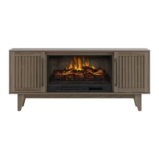
Rosalie 65in. Infrared Media Electric Fireplace
OR
Questions, problems, missing parts? Before returning to the store,
call Customer Service
1-866-942-5362
Pacific Standard Time: 8:30 a.m. - 4:30 p.m., Monday - Friday
Or visit our web site 24 hours a day, 7 days a week for product assistance at
www.whalenfurniture.com
Or e-mail your request to parts@whalenfurniture.com
THANK YOU
We appreciate the trust and confidence you have placed in Scott Living by Drew & Jonathan through the purchase of this
electric fireplace/heater. We strive to continually create quality products designed to enhance your home. Visit us online to
see our full line of products available for your home improvement needs.
Thank you for choosing Scott Living by Drew & Jonathan!
Advertisement
Table of Contents

Related Manuals for drew & jonathan SCOTT LIVING HDSLFP65W-4A


Summary of Contents for drew & jonathan SCOTT LIVING HDSLFP65W-4A
- Page 1 Model # HDSLFP65W-4A OMSID # 320643166 # HDSLFP65W-4B # 320643195 ASSEMBLY INSTRUCTIONS Rosalie 65in. Infrared Media Electric Fireplace Questions, problems, missing parts? Before returning to the store, call Customer Service 1-866-942-5362 Pacific Standard Time: 8:30 a.m. - 4:30 p.m., Monday - Friday Or visit our web site 24 hours a day, 7 days a week for product assistance at www.whalenfurniture.com Or e-mail your request to parts@whalenfurniture.com...
- Page 2 Table of Contents Table of Contents Hardware Included Safety Information Package Contents Maximum Recommended Weight Loads Assembly Warranty Care and Maintenance Pre-Assembly Caring for Wood Furniture Planning Assembly Cleaning the Fireplace Trim Tools Required Safety Information Fits up to most 190.5 cm / 75 in. diagonal flat-panel TVs Please read and understand these instructions before Maximum load 45.4 kg / 100 lb assembling and using this console.
- Page 3 Pre-Assembly (continued) HARDWARE INCLUDED NOTE: Hardware not shown to actual size. Part Description Quantity Part Description Quantity Insert screw 10+1 extra Handle Wood dowel 18+1 extra Handle bolt Cam lock 13+1 extra Shelf Support 8+1 extra Cam bolt 13+1 extra L-shaped bracket Washer head screw 26+1 extra...
- Page 4 Pre-Assembly (continued) PACKAGE CONTENTS Part Description Quantity Part Description Quantity Heater Right front / Left back leg Left upright arm Left side panel Right upright arm Left partition panel Connector strap Right partition panel Ember bed Right side panel Left log Left door Right log Right door...
- Page 5 Assembly Preparing top and partition panels assembly NOTE: Do not fully tighten all bolts until you finish assembling all parts. Once assembled, go back and fully tighten all bolts. This will make the assembly easier. □ Unpack the unit and confirm that you have all the hardware and required parts. Assemble the unit on a carpeted floor or the empty carton to avoid any scratches.
- Page 6 Assembly (continued) Attaching legs □ Attach the legs (M and N) to the bottom corners of the bottom panel (L) with two bolts (GG), two lock washers (HH) and two flat washers (II) per leg. Attaching top front stretcher NOTE: Refer to the cam lock assembling guide drawings in this step for further clarification on how to properly install cam locks.
- Page 7 Assembly (continued) Attaching top panel □ Using the wood dowels as a guide, align and attach the top panel (K) to the previous assembly by engaging four cam locks (CC). Attaching side panels □ Orient and attach two side panels (O and R) to the top panel (K) by engaging four cam locks (CC) as shown. The hinge mounting holes face inward and are located at front side...
- Page 8 Assembly (continued) Assembling base □ Using the wood dowels as a guide, firmly press the previous assembly to the bottom panel (L) and fasten them into place with eight long flat head screws (FF). Fastening top front stretcher □ Ask for assistance to flip the previous assembly around at its front edge. □...
- Page 9 Assembly (continued) Attaching back panels □ Now, go back and securely tighten all the cam locks and screws. Make sure all the parts are tight and there are no gaps between the parts. This will help keep the unit square. □...
- Page 10 Assembly (continued) Installing door handles □ Attach one handle (LL) to the front side of each door (S and T) with two handle bolts (MM). Attaching door panels □ Ask for assistance to lift the assembled unit upright and position it near the final location. □...
- Page 11 Assembly (continued) Attaching adjustable shelves □ Open the doors and insert four shelf supports (NN) in the holes at the desired height inside each side compartment. Make sure you place the four shelf supports at the same level to make the shelf level. □...
- Page 12 Assembly (continued) Attaching upright arms IMPORTANT NOTE: . See BILT for video instructions. Use hand screwdriver, not power driver to assemble fireplace insert □ See figure A: Fasten upper 2 screws (AA) through the upright arm (C) into the heater (A) until tight. □...
- Page 13 Assembly (continued) Positioning ember bed □ Set the ember bed (E) onto the heater (A) as shown. □ Push ember bed forward against the front flange of heater. □ Position the USB cable as shown below. USB cable Attaching wall panels □...
- Page 14 Assembly (continued) Connecting ember bed cable to heater □ Fully plug the USB connector of the ember bed (E) into the back port of heater (A). Inserting the glass □ Slide the glass (I) into the inner U-channels on both upright arms (B and C) until the glass sits onto the heater (A). If needed, push top of upright arms in or out to accommodate glass.
- Page 15 Assembly (continued) Positioning connector strap □ Position top connector strap (D) over the glass (I) and upright arms (B and C). Follow orientation shown below. The bevel edge faces inside the unit. Attaching connector strap □ Fasten connector strap (D) to both upright arms (B and C) using two screws (AA) as show below. Holes must be in line for screw to pass through.
- Page 16 Assembly (continued) Installing the fireplace insert □ Lift the fireplace insert carefully into the back of the assembled mantel and centre it in the opening. □ Use the pilot holes as a guide, fasten two large L-shaped brackets (OO) onto the firebox holder (X) with four pan head screws (PP).
- Page 17 Assembly (continued) Interchanging door insert panels □ To change door panels, loosen the screws on the inside of the door and rotate the clips to remove the panel. Replace with the desired panel, then rotate clips to secure the panel within the door frame and tighten screws. NOTE: The glass door panels are pre-attached when shipping.
- Page 18 Care and Maintenance A touch-up pen has been provided to minimize the small nicks or scratches that may occur during assembly or shipping. To clean and care for your furniture: □ Use a soft, clean cloth that will not scratch the surface when dusting. □...
- Page 19 We’re not happy unless you’re happy, so we offer a 30-day Love It Guarantee. If for any reason you don’t love your Scott Living product, you can return it to your place of purchase within 30 days of the date on your receipt for a full refund — no questions asked. RETURN POLICY FOR CUSTOM ITEMS VARY.
- Page 21 OMSID n 320643166 Modèle n HDSLFP65W-4A 320643195 HDSLFP65W-4B INSTRUCTIONS DE MONTAGE Meuble multimédia de 1,65 m avec foyer électrique à infrarouge Rosalie Vous avez des questions ou des problèmes? Certaines pièces sont manquantes? Avant de vous rendre au magasin, communiquez avec le service à la clientèle de 1-866-942-5362 Heure normale du Pacifique, entre 8 h 30 et 16 h 30, du lundi au vendredi Vous pouvez également visiter notre site Web 24 heures par jour, 7 jours sur 7 pour obtenir de l’aide sur le produit...
-
Page 22: Table Of Contents
Table des matières Table des matières ..............2 Matériel fourni ................3 Consignes de sécurité ............. 2 Contenu de l’emballage ............4 Poids maximal supporté ............2 Assemblage ................5 Garantie ..................2 Entretien ..................18 Pré-assemblage ................ 2 Entretien de votre meuble en bois ........18 Plan de montage .............. -
Page 23: Matériel Fourni
Pré-Assemblage (suite) MATÉRIEL FOURNI REMARQUE : le matériel n’est pas affiché à l’échelle de grandeur réelle. Pièce Description Quantité Pièce Description Quantité Vis de foyer 10+1 extra Poignée Chevilles en bois 18+1 extra Boulon de poignée Verrou à came 13+1 extra Support d’étagère 8+1 extra Boulons à... -
Page 24: Contenu De L'emballage
Pré-assemblage (suite) CONTENU DE L’EMBALLAGE Pièce Description Quantité Pièce Description Quantité Pied avant droite / arrière Radiateur gauche Bras verticaux gauche Panneau latéral gauche Bras verticaux droit Paroi gauche inférieur l’attache du connecteur Paroi droit inférieur Lit de braises Panneau latéral droit Bûches gauche Porte gauche Bûches droite... -
Page 25: Assemblage
Assemblage Préparation de l’assemblage des panneaux supérieur et paroi REMARQUE : Ne pas complètement serrer les boulons avant d’avoir terminé l’assemblage de toutes les pièces. Une fois assemblées, revenir en arrière et serrer tous les boulons. Cela facilitera l’assemblage. □ Déballez l’unité... - Page 26 Assemblage (suite) Fixation des pieds □ Fixez les pieds (M et N) aux coins du panneau inférieur (L) avec deux boulons (GG), deux rondelles de blocage (HH) et deux rondelles plates (II) par pied. Fixation de la châssis avant supérieur REMARQUE : Reportez-vous aux dessins du guide d’assemblage des verrous à...
- Page 27 Assemblage (suite) Fixation du panneau supérieur □ En utilisant les chevilles en bois comme guide, alignez et fixez le panneau supérieur (K) aux l’assemblage précédent en engageant 4 verrous à came (CC). Fixer des panneaux latéraux □ Orientez et fixez deux panneaux latéraux (O et R) au panneau supérieur (K) en engageant 4 verrous à came (CC) comme illustré.
- Page 28 Assemblage (suite) Fixer la base □ En utilisant les chevilles en bois comme guide, appuyez fermement sur les parois assemblées contre le panneau inférieur (L) et fixez-les avec 8 vis à tête plate longues (FF). Fixation du châssis avant □ Demandez de l’aide pour retourner l’assemblage précédent sur ses bords avant.
- Page 29 Assemblage (suite) Installer les panneaux arrière □ Maintenant, revenez et serrez solidement tous les verrous à came et vis. Assurez-vous que toutes les pièces sont bien serrées et qu’il n’y a pas d’espace entre les pièces. Cela permettra de maintenir l’unité à l’équerre. □...
- Page 30 Assemblage (suite) Installation des poignées de porte □ Fixez une poignée (LL) à l’avant de chaque porte (S et T) à l’aide de deux boulons de poignée (MM). Fixer les panneaux de porte □ Demandez de l’aide pour soulever l’unité de montage debout et la positionner près de l’emplacement final. □...
- Page 31 Assemblage (suite) Fixer les étagères réglables □ Ouvrez les portes et insérez quatre supports d’étagère (NN) dans les trous à la hauteur souhaitée à l’intérieur de chaque compartiment latéral. Assurez-vous de placer les quatre supports d’étagère au même niveau afin que l’étagère ne soit à...
- Page 32 Assemblage (suite) Fixation des bras verticaux assemblez le foyer encastrable avec un tournevis à main au lieu d’un REMARQUE IMPORTANTE : tournevis électrique . Voir BILT pour les instructions video. □ Voir figure A: Serrez les 2 vis supérieures (AA) à travers le bras vertical (C) dans le radiateur (A) jusqu’à ce qu’elles soit bien serrées.
- Page 33 Assemblage (suite) Positionnement du lit de braises □ Placez le lit de braises (E) sur le radiateur (A) comme illustré. □ Poussez le lit de braises vers l’avant contre la bride avant du radiateur. □ Positionnez le câble USB comme indiqué ci-dessous. Câble USB Fixation du panneau mural □...
- Page 34 Assemblage (suite) Connexion du câble du lit de braises au radiateur □ Branchez complètement le connecteur USB du lit de braises (E) dans le port arrière du radiateur (A). Insertion du verre □ Faites glisser le verre (I) dans les canaux en U intérieurs des deux bras verticaux (B et C) jusqu’à ce que le verre repose sur le radiateur (A).
- Page 35 Assemblage (suite) Positionnement de l’attache du connecteur □ Placez l’attache du connecteur (D) supérieur sur le verre (I) et les bras verticaux (B et C). Suivez l’orientation indiquée ci-dessous. Le bord biseauté doit faire face à l’intérieur de l’appareil. Fixation de l’attache du connecteur □...
- Page 36 Assemblage (suite) Installer l’insertion de cheminée □ Soulevez délicatement le foyer encastrable à l’arrière du manteau assemblé et centrez-le dans l’ouverture. □ Utilisez les trous pilotes comme guide, fixez deux supports métalliques en L (OO) sur le support de foyer (X) avec quatre vis à...
- Page 37 Assemblage (suite) L’échange du panneaux d’insertion de porte □ Pour changer les panneaux de porte, desserrez les vis à l’intérieur de la porte et tournez les clips pour retirer le panneau. Remplacez-le par le panneau souhaité, puis faites pivoter les clips pour fixer le panneau dans le cadre de la porte et serrez les vis.
-
Page 38: Entretien
Entretien Un crayon à retouche est fourni pour minimiser les petites marques ou éraflures pouvant survenir lors du montage ou de l’expédition. Entretien de votre meuble : □ Utilisez un tissu doux et propre qui n’égratignera pas la surface lors de l’époussetage. □... - Page 39 Nous ne sommes satisfaits que si vous l'êtes, c'est pourquoi nous offrons une Garantie Love It de 30 jours. Si, pour une raison quelconque, vous n'aimez pas votre produit Scott Living, vous pouvez le retourner dans votre magasin dans un délai de 30 jours à compter de la date figurant sur votre reçu pour un remboursement complet - sans poser de questions.
- Page 41 Modelo # HDSLFP65W-4A OMSID # 320643166 # HDSLFP65W-4B # 320643195 INSTRUCCIONES DE ENSAMBLE Consola de 65” con chimenea eléctrica infrarroja para medios Rosalie ¿Preguntas, problemas, partes que falten? Antes de regresar a la tienda llame al servicio al cliente 1-866-942-5362 Hora estándar del Pacífico: 8:30 a.m.
- Page 42 Lista de contenidos Lista de contenidos Ferretería incluida Información de seguridad Contenido del paquete Maximo peso recomendado Ensamble Garantía Cuidado y mantenimiento Pre-ensamble Cuidando su mueble de madera Planeando el ensamble Limpiando el borde de la chimenea Herramientas requeridas Información de seguridad Por favor lea y entienda estas instrucciones antes de Permite TVs de pantalla diagonal de hasta 190.5 cm / 75 pulgadas ensamblar y usar esta consola.
- Page 43 Pre-ensamble (continuación) FERRETERÍA INCLUIDA NOTA: La ferretería no está mostrada al tamaño real. Parte Descripción Cantidad Parte Descripción Cantidad Perno para insertar 10+1 extra Manija Clavija de madera 18+1 extra Perno para manija Tuerca de fijación 13+1 extra Soporte para repisa 8+1 extra Perno de fijación 13+1 extra...
- Page 44 Pre-ensamble (continuación) CONTENIDO DEL PAQUETE Parte Descripción Parte Descripción Cantidad Cantidad Pata derecha frontal / Calentón izquierda posterior Brazo izquierdo vertical Panel izquierdo Brazo derecho vertical Panel divisor izquierdo Correa conectora Panel divisor derecho Lecho de brasas Panel derecho Tronco izquierdo Puerta izquierda Tronco derecho Puerta derecha...
- Page 45 Ensamble Preparando el ensamble de los paneles superior y divisores NOTA: Por favor no apriete completamente todos los pernos, hasta que termine con el ensamble de las partes. Después asegúrese de apretar todos los pernos. Esto hará el ensamble más fácil. □...
- Page 46 Ensamble (continuación) Adjuntando las patas □ Adjuntar las patas (M y N) a las esquinas del panel inferior (L) con 2 pernos (GG), 2 arandelas de presión (HH) y 2 arandelas planas (II) por pata. Adjuntando el soporte superior frontal NOTA: Consultar los dibujos guías de las tuercas de fijación en esté...
- Page 47 Ensamble (continuación) Adjuntar el panel superior □ Usando las clavijas de madera como guía, alinear y adjuntar el panel superior (K) al ensamble previo empleando 4 tuercas de fijación (CC). Adjuntando los paneles laterales □ Orientar y adjuntar dos paneles laterales (O y R) al panel superior (K) empleando 4 tuercas de fijación (CC) como se muestra.
- Page 48 Ensamble (continuación) Ensamblado la base □ Usando las clavijas de madera como guía, presionar el ensamble previo al panel inferior (L) y sujetar en su lugar con 8 pernos de cabeza plana largos (FF). Sujetando el soporte superior frontal □ Pedir aistencia para voltear el ensamble previo en sus bordes frontales.
- Page 49 Ensamble (continuación) Adjuntando los paneles posteriores □ Ahora, volver y apretar todas las tuercas de fijación y los pernos. Asegurar que todas las partes estén apretadas y de que no hay huecos entre las partes. Esto ayudara a mantener la unidad cuadrada. □...
- Page 50 Ensamble (continuación) Instalando las manijas para puertas □ Adjuntar una manija (LL) al lado frontal de cada puerta (S y T) con 2 pernos para manija (MM). Adjuntando los paneles puerta □ Pedir por asistencia para poner la unidad ensamblada en posición vertical y cerca de la posición final. □...
- Page 51 Ensamble (continuación) Adjuntando las repisas ajustables □ Abrir las puertas e insertar 4 soportes para repisa (NN) en los agujeros a la altura deseada dentro de cada compartimiento lateral. Asegurar de poner 4 soportes para repisa en el mismo nivel para hacer un nivel de repisa. □...
- Page 52 Ensamble (continuación) Adjuntando los brazos verticales IMPORTANTE NOTA: Usar el desarmador manual, no usar un taladro para ensamblar el inserto de chimenea. Vea BILT para instrucciones por medio de un video □ Vea la figura A: Sujetar 2 pernos superiores (AA) a través del brazo vertical (C) hacia el calentón (A) hasta apretar. □...
- Page 53 Ensamble (continuación) Posicionando el lecho de brasas □ Poner el lecho de brasas (E) sobre el calentón (A) como se muestra. □ Empujar el lecho de brasas hacia adelante contra la pestaña frontal del calentón. □ Posicionar el cable USB como se muestra abajo. Cable USB Adjuntando el panel pared □...
- Page 54 Ensamble (continuación) Conectando el cable del lecho de brasas al calentón □ Enchufar completamente el conector USB al lecho de brasas (E) en el puerto posterior del calentón (A). Insertando el vidrio □ Deslizar el vidrio (I) en los canales U internos en ambos brazos verticales (B y C) hasta que el vidrio esté sobre el calentón (A).
- Page 55 Ensamble (continuación) Posicionando la correa de conexión □ Posicionar la correa de conexión superior (D) sobre el vidrio (I) y brazos verticales (B y C). Seguir la orientación mostrada abajo. El borde bisel apunta hacia adentro de la unidad. Adjuntando la correa conector □...
- Page 56 Ensamble (continuación) Instalando el inserto de chimenea □ Levantar el inserto de chimenea en la parte posterior del delantal ensamblado y centrar en la abertura. □ Usando los agujeros pilotos como guía, sujetar 2 soportes L (OO) sobre el soporte de la caja de fuego (X) con 4 pernos de cabeza redonda (PP).
- Page 57 Ensamble (continuación) Intercambiando los insertos para puerta □ Para cambiar los paneles puerta, aflojar los pernos en la parte interior de la puerta y rotar los clips para retirar el panel. Reemplazar con el panel deseado, luego rotar los clips para asegurar el panel dentro del marco de la puerta y apretar los pernos.
- Page 58 Cuidado y mantenimiento Un plumón es provisto para en caso de pequeños golpes o rayaduras que puedan ocurrir durante el ensamble o envió. Para limpiar y cuidar su mueble: □ Use una toalla suave y limpia que no rayara la superficie al limpiar. □...
- Page 59 No estamos contentos a menos que usted esté contento, por lo que ofrecemos una Garantía de 30 días Love It. Si por alguna razón no le gusta su producto Scott Living, puede devolverlo a su lugar de compra dentro de los 30 días siguientes a la fecha de su recibo para un reembolso completo sin preguntas.
Need help?
Do you have a question about the SCOTT LIVING HDSLFP65W-4A and is the answer not in the manual?
Questions and answers