Table of Contents
Advertisement
Quick Links
Advertisement
Table of Contents

Related Manuals for Dragino RS485-LN


Summary of Contents for Dragino RS485-LN
- Page 1 RS485-LN -- RS485 to LoRaWAN Converter User Manual Document Version: 1.0.1 Image Version: v1.0 Version Description Date Release 2019-Dec-8 1.0.1 Improve product photos and network structure 2019-Dec-30 RS485 to LoRaWAN Converter User Manual 1 / 29...
-
Page 2: Table Of Contents
How to change the LoRa Frequency Bands/Region? ..............23 How to set up RS485-LN to work in other 8 channel mode in US915, AU915, CN470 bands? . 24 How to set up RS485-LN to work with Single Channel Gateway such as LG01/LG02? ..... 25 Trouble Shooting ........................ - Page 3 Packing Info ..........................27 Support ........................... 28 Reference ..........................29 RS485 to LoRaWAN Converter User Manual 3 / 29...
-
Page 4: Introduction
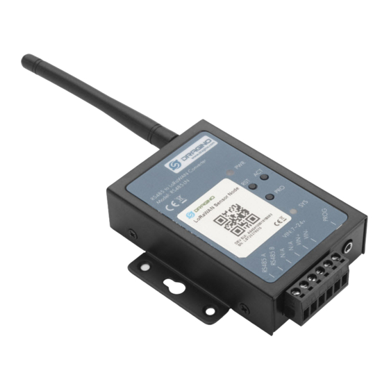
1. Introduction 1.1 What is RS485-LN RS485 to LoRaWAN Converter The Dragino RS485-LN is a RS485 to LoRaWAN Converter. It converts the RS485 signal into LoRaWAN wireless signal which simplify the IoT installation and reduce the installation/maintaining cost. RS485-LN allows user to monitor / control RS485 devices and reach extremely long ranges. It provides ultra-long range spread spectrum communication and high interference immunity whilst minimizing current consumption. -
Page 5: Specifications
1.2 Specifications Hardware System: STM32L072CZT6 MCU SX1276/78 Wireless Chip Power Consumption (exclude RS485 device): Idle: 32mA@12v 20dB Transmit: 65mA@12v Interface for Model: RS485 Power Input 7~ 24V DC. LoRa Spec: Frequency Range: ... -
Page 6: Applications
1.4 Applications Smart Buildings & Home Automation Logistics and Supply Chain Management Smart Metering Smart Agriculture Smart Cities Smart Factory RS485 to LoRaWAN Converter User Manual 6 / 29... -
Page 7: Firmware Change Log
RS485-LN Image files – Download link Image v1.0 Release 2. Power ON Device The RS485-LN can be powered by 7 ~ 24V DC power source. Connection as below Power Source VIN to RS485-LN VIN+ Power Source GND to RS485-LN VIN- Once there is power, the RS485-LN will be on. -
Page 8: Operation Mode
3. Operation Mode 3.1 How it works? The RS485-LN is configured as LoRaWAN OTAA Class C mode by default. It has OTAA keys to join network. To connect a local LoRaWAN network, user just need to input the OTAA keys in the network server and power on the RS485-LN. - Page 9 . So what we need to now is only configure the TTN: Step 1: Create a device in TTN with the OTAA keys from RS485-LN. Each RS485-LN is shipped with a sticker with unique device EUI: RS485 to LoRaWAN Converter User Manual...
- Page 10 Add APP EUI in the application. Add APP KEY and DEV EUI Step 2: Power on RS485-LN and it will auto join to the TTN network. After join success, it will start to upload message to TTN and user can see in the panel.
-
Page 11: Configure Commands To Read Data
There are plenty of RS485 devices in the market and each device has different command to read the valid data. To support these devices in flexible, RS485-LN supports flexible command set. User can use AT Commands to configure what commands RS485-LN should send for each sampling and how to handle the output from RS485 devices. - Page 12 We want to get the DI status & DO status from RS485 IO and upload to LoRaWAN server, we might have different RS485-LN to connect to different RS485 devices and upload different payloads, so it will be good to use different Payload Version to tell the LoRaWAN server what devices we have connected.
- Page 13 Final Payload to be uplink will be: PAYVER + CMD1 VALID RETURN + CMD2 VALID RETURN RS485 to LoRaWAN Converter User Manual 13 / 29...
-
Page 14: Uplink Payload
Example screen shot: AT+DATAUP=1,2 The uplink screen shot is: 3.4 Uplink Payload Size(bytes) Length depends on the return from the commands Value PAYLOAD_VER If the valid payload is too long and exceed the maximum support payload length in server, server will show payload not provided in the LoRaWAN server. - Page 15 Example Downlink payload setting in TTN: Type Code 0x04 If payload = 0x04FF, it will reset the RS485-LN. Type Code 0x08 If payload = 0x08FF, RS485-LN will immediately send an uplink. RS485 to LoRaWAN Converter User Manual 15 / 29...
- Page 16 RS485 to LoRaWAN Converter User Manual 16 / 29...
-
Page 17: Buttons
Always on if there is power After device is powered on, the SYS will fast blink in GREEN for 5 times, means RS485-LN start to join LoRaWAN network. If join success, SYS will be on GREEN for 5 seconds. SYS will... -
Page 18: Use At Command
4. Use AT Command 4.1 Access AT Command RS485-LN supports AT Command set. User can use a USB to TTL adapter plus the 3.5mm Program Cable to connect to RS485-LN to use AT command, as below. In PC, User needs to set... - Page 19 More detail AT Command manual can be found at AT Command Manual RS485 to LoRaWAN Converter User Manual 19 / 29...
-
Page 20: Common At Command Sequence
4.2 Common AT Command Sequence 4.2.1 Multi-channel ABP mode (Use with SX1301/LG308) If device has not joined network yet: AT+FDR AT+NJM=0 If device already joined network: AT+NJM=0 4.2.2 Single-channel ABP mode (Use with LG01/LG02) AT+FDR Reset Parameters to Factory Default, Keys Reserve... - Page 21 Hold down the PRO button and then momentarily press the RST reset button and the SYS led will change from OFF to ON, While SYS LED is RED ON, it means the RS485-LN is ready to be program. RS485 to LoRaWAN Converter User Manual...
- Page 22 Board detected HOLD PRO then press the RST button, SYS will be ON, then click next RS485 to LoRaWAN Converter User Manual 22 / 29...
-
Page 23: How To Change The Lora Frequency Bands/Region
Notice: In case user has lost the program cable. User can hand made one from a 3.5mm cable. The pin mapping is: 5.2 How to change the LoRa Frequency Bands/Region? User can follow the introduction for how to upgrade image. -
Page 24: How To Set Up Rs485-Ln To Work In Other 8 Channel Mode In Us915, Au915, Cn470 Bands
5.3 How to set up RS485-LN to work in other 8 channel mode in US915, AU915, CN470 band By default, the frequency bands US915, AU915, CN470 works in 8~15 (CHE=2) frequencies. User can set to the frequencies to work in other channels, by using the AT+CHE command. -
Page 25: How To Set Up Rs485-Ln To Work With Single Channel Gateway Such As Lg01/Lg02
5.4 How to set up RS485-LN to work with Single Channel Gateway such as LG01/LG02? In this case, users need to set RS485-LN to work in ABP mode & transmit in only one frequency. Assume we have a LG02 working in the frequency 868400000 now , below is the step. - Page 26 Step2: Run AT Command to make LT work in Single frequency & ABP mode. Below is the AT commands: AT+FDR Reset Parameters to Factory Default, Keys Reserve AT+NJM=0 Set to ABP mode AT+ADR=0 Set the Adaptive Data Rate Off...
-
Page 27: Trouble Shooting
IN865: frequency bands IN865 CN779: frequency bands CN779 8. Packing Info Package Includes: RS485-LN x 1 Stick Antenna for LoRa RF part x 1 Program cable x 1 RS485 to LoRaWAN Converter User Manual 27 / 29... - Page 28 Dimension and weight: Device Size: 13.5 x 7 x 3 cm Device Weight: 105g Package Size / pcs : 14.5 x 8 x 5 cm Weight / pcs : 170g 9. Support Support is provided Monday to Friday, from 09:00 to 18:00 GMT+8. Due to different timezones we cannot offer live support.
- Page 29 10. Reference Product Page Image Download AT Command Manual Hardware Source RS485 to LoRaWAN Converter User Manual 29 / 29...
Need help?
Do you have a question about the RS485-LN and is the answer not in the manual?
Questions and answers