
Related Manuals for Dragino RS485-LN


Summary of Contents for Dragino RS485-LN
- Page 1 RS485-LN -- RS485 to LoRaWAN Converter User Manual Document Version: 1.4 Image Version: v1.3.0 Version Description Date RS485 to LoRaWAN Converter User Manual 1 / 30...
- Page 2 Release 2019-Dec-8 1.0.1 Improve product photos and network structure 2019-Dec-30 1.0.2 Add AT Command to set UART parity Upgrade manual for v1.1 firmware version 2020-Feb-19 Add downlink command 0x09, Add Command AT+CMDDL 2020-May-16 Remove FAQ for LG01, Add FAQ for slave numbers, Add Case Study Link.
-
Page 3: Table Of Contents
Introduction ..........................5 What is RS485-LN RS485 to LoRaWAN Converter ..............5 Specifications ..........................6 Features ............................6 Applications ..........................6 Hardware Change log ......................... 7 Installation ..........................7 Power ON Device ........................8 Operation Mode ........................9 How it works? ..........................9 Example to join LoRaWAN network .................... - Page 4 Use AT Command ........................27 Access AT Command ......................... 27 Trouble Shooting ........................29 Downlink doesn’t work, how to solve it? .................. 29 Why I can’t join TTN V3 in US915 /AU915 bands? ..............29 Order Info ..........................29 Packing Info ..........................
-
Page 5: Introduction
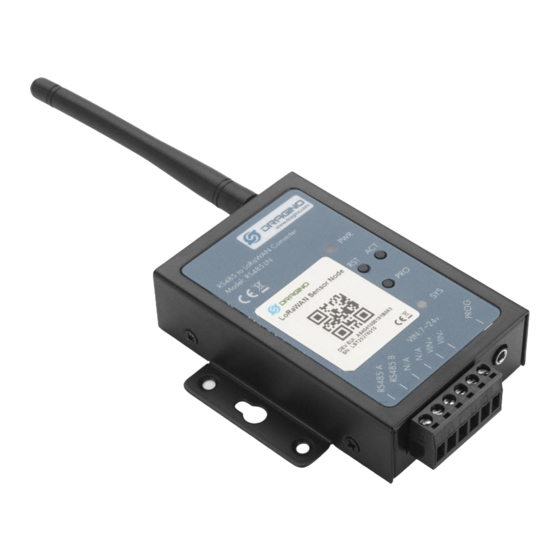
1. Introduction 1.1 What is RS485-LN RS485 to LoRaWAN Converter The Dragino RS485-LN is a RS485 to LoRaWAN Converter. It converts the RS485 signal into LoRaWAN wireless signal which simplify the IoT installation and reduce the installation/maintaining cost. RS485-LN allows user to monitor / control RS485 devices and reach extremely long ranges. It provides ultra-long range spread spectrum communication and high interference immunity whilst minimizing current consumption. -
Page 6: Specifications
1.2 Specifications Hardware System: ➢ STM32L072CZT6 MCU ➢ SX1276 Wireless Chip ➢ Power Consumption (exclude RS485 device): Idle: 32mA@12v 20dB Transmit: 65mA@12v Interface for Model: ➢ RS485 ➢ Power Input 7~ 24V DC. LoRa Spec: ➢ 168 dB maximum link budget. -
Page 7: Hardware Change Log
Smart Agriculture ✓ Smart Cities ✓ Smart Factory 1.5 Hardware Change log v1.2 Add External Interrupt Pin. v1.0 Release 1.6 Installation Please ask a professional engineer to install the RS485-LN. RS485 to LoRaWAN Converter User Manual 7 / 30... -
Page 8: Power On Device
2. Power ON Device The RS485-LN can be powered by 7 ~ 24V DC power source. Connection as below ✓ Power Source VIN to RS485-LN VIN+ ✓ Power Source GND to RS485-LN VIN- Once there is power, the RS485-LN will be on. -
Page 9: Operation Mode
3. Operation Mode 3.1 How it works? The RS485-LN is configured as LoRaWAN OTAA Class C mode by default. It has OTAA keys to join network. To connect a local LoRaWAN network, user just need to input the OTAA keys in the network server and power on the RS485-LN. - Page 10 RS485 to LoRaWAN Converter User Manual 10 / 30...
- Page 11 User can enter this key in their LoRaWAN Server portal. Below is TTN V3 screen shot: Add APP EUI in the application. RS485 to LoRaWAN Converter User Manual 11 / 30...
- Page 12 RS485 to LoRaWAN Converter User Manual 12 / 30...
- Page 13 You can also choose to create the device manually. RS485 to LoRaWAN Converter User Manual 13 / 30...
-
Page 14: Configure Commands To Read Data
Add APP KEY and DEV EUI Step 2: Power on RS485-LN and it will auto join to the TTN V3 network. After join success, it will start to upload message to TTN V3 and user can see in the panel. -
Page 15: Configure Rs485 Sensors
3.3.2 Configure RS485 sensors Some sensors might need to configure before normal operation. User can configure such sensor via PC and RS485 adapter or through RS485-LN AT Commands AT+CFGDEV. Each AT+CFGDEV equals to send a RS485 command to sensors. This command will only run when user input it and won’t run during each sampling. -
Page 16: Configure Read Commands For Each Sampling
This section describes how to achieve above goals. During each sampling, the RS485-LN can support 15 commands to read sensors. And combine the return to one or several uplink payloads. Each RS485 commands include two parts: What commands RS485-LN will send to the RS485 sensors. - Page 17 In the RS485-LN, we should use this command AT+COMMAND1=01 03 0B B8 00 02,1 for the same. AT+DATACUTx : This command defines how to handle the return from AT+COMMANDx, max return length is 45 bytes. AT+DATACUTx=a,b,c a: length for the return of AT+COMMAND ...
-
Page 18: Compose The Uplink Payload
3.3.4 Compose the uplink payload Through AT+COMMANDx and AT+DATACUTx we got valid value from each RS485 commands, Assume these valid value are RETURN1, RETURN2, .., to RETURNx. The next step is how to compose the LoRa Uplink Payload by these RETURNs. The command is AT+DATAUP. - Page 19 Examples: AT+DATAUP=1 Compose the uplink payload with value returns in sequence and send with Multiply UPLINKs. Final Payload is PAYVER + PAYLOAD COUNT + PAYLOAD# + DATA 1) PAYVER: Defined by AT+PAYVER 2) PAYLOAD COUNT: Total how many uplinks of this sampling.
-
Page 20: Uplink On Demand
RS485-LN support external Interrupt uplink since hardware v1.2 release. Connect the Interrupt pin to RS485-LN INT port and connect the GND pin to V- port. When there is a high voltage (Max 24v) on INT pin. Device will send an uplink packet. -
Page 21: Configure Rs485-Ln Via At Or Downlink
XX XX XX XX: RS485 command total NN bytes YY: How many bytes will be uplink from the return of this RS485 command, if YY=0, RS485-LN will execute the downlink command without uplink; if YY>0, RS485-LN will uplink total YY bytes from the output of this... -
Page 22: Set Payload Version
RS485 network, the final byte 00 means this command don’t need to acquire output. Set Payload version This is the first byte of the uplink payload. RS485-LN can connect to different sensors. User can set the PAYVER field to tell server how to decode the current payload. -
Page 23: Fast Command To Handle Modbus Device
XX XX XX XX: AT+COMMAND or AT+DATACUT command YY: If YY=0, RS485-LN will execute the downlink command without uplink; if YY=1, RS485-LN will execute an uplink after got this command. Example: AF 03 01 06 0A 05 00 04 00 01... -
Page 24: Rs485 Command Timeout
RS485 command timeout Some Modbus device has slow action to send replies. This command is used to configure the RS485-LN to use longer time to wait for their action. Default value: 0, range: 0 ~ 65 seconds ➢ AT Command:... -
Page 25: Set Serial Communication Parameters
AT+CMDEAR=mm,nn mm: start position of erase ,nn: stop position of erase Etc. AT+CMDEAR=1,10 means erase AT+COMMAND1/AT+DATACUT1 to AT+COMMAND10/AT+DATACUT10 Example screen shot after clear all RS485 commands. The uplink screen shot is: ➢ Downlink Payload: 0x09 aa bb same as AT+CMDEAR=aa,bb... -
Page 26: Leds
Always on if there is power After device is powered on, the SYS will fast blink in GREEN for 5 times, means RS485-LN start to join LoRaWAN network. If join success, SYS will be on GREEN for 5 seconds. SYS will... -
Page 27: Case Study
5. Use AT Command 5.1 Access AT Command RS485-LN supports AT Command set. User can use a USB to TTL adapter plus the 3.5mm Program Cable to connect to RS485-LN to use AT command, as below. In PC, User needs to set... - Page 28 More detail AT Command manual can be found at AT Command Manual RS485 to LoRaWAN Converter User Manual 28 / 30...
- Page 29 ➢ KZ865: frequency bands KZ865 8. Packing Info Package Includes: ✓ RS485-LN x 1 ✓ Stick Antenna for LoRa RF part x 1 ✓ Program cable x 1 Dimension and weight: ✓ Device Size: 13.5 x 7 x 3 cm ✓...
- Page 30 9. FCC Caution: Any Changes or modifications not expressly approved by the party responsible for compliance could void the user's authority to operate the equipment. This device complies with part 15 of the FCC Rules. Operation is subject to the following two conditions: (1) This device may not cause harmful interference, and (2) this device must accept any interference received, including interference that may cause undesired operation.
Need help?
Do you have a question about the RS485-LN and is the answer not in the manual?
Questions and answers