
Related Manuals for Dragino RS485-LN


Summary of Contents for Dragino RS485-LN
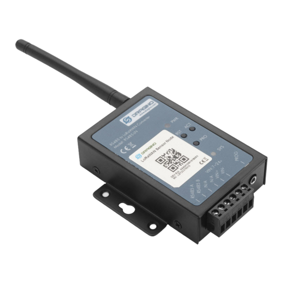
- Page 1 RS485-LN – RS485 to LoRaWAN Converter User Manual last modified by Bei Jinggeng on 2022/07/08 16:50...
-
Page 2: Table Of Contents
User Manual for LoRaWAN End Nodes - RS485-LN – RS485 to LoRaWAN Converter User Manual Table of Contents 1.Introduction ................................... 4 1.1 What is RS485-LN RS485 to LoRaWAN Converter ....................4 1.2 Specifications ................................. 5 1.3 Features ..................................6 1.4 Applications ..................................6 1.5 Firmware Change log .............................. - Page 3 User Manual for LoRaWAN End Nodes - RS485-LN – RS485 to LoRaWAN Converter User Manual Table of Contents: • 1.Introduction • 1.1 What is RS485-LN RS485 to LoRaWAN Converter • 1.2 Specifications • 1.3 Features • 1.4 Applications • 1.5 Firmware Change log •...
-
Page 4: Introduction
User Manual for LoRaWAN End Nodes - RS485-LN – RS485 to LoRaWAN Converter User Manual • 3. Operation Mode • 3.1 How it works? • 3.2 Example to join LoRaWAN network • 3.3 Configure Commands to read data • 3.3.1 onfigure UART settings for RS485 or TTL communication •... -
Page 5: Specifications
For data uplink, RS485-LN sends user-defined commands to RS485 devices and gets the return from the RS485 devices. RS485-LN will process these returns according to user-define rules to get the final payload and upload to LoRaWAN server. For data downlink, RS485-LN runs in LoRaWAN Class C. -
Page 6: Features
User Manual for LoRaWAN End Nodes - RS485-LN – RS485 to LoRaWAN Converter User Manual LoRa Spec: • Frequency Range: • Band 1 (HF): 862 ~ 1020 Mhz • Band 2 (LF): 410 ~ 528 Mhz • 168 dB maximum link budget. -
Page 7: Operation Mode
3.1 How it works? The RS485-LN is configured as LoRaWAN OTAA Class C mode by default. It has OTAA keys to join network. To connect a local LoRaWAN network, user just need to input the OTAA keys in the network server and power on the RS485-LN. - Page 8 User Manual for LoRaWAN End Nodes - RS485-LN – RS485 to LoRaWAN Converter User Manual The RS485-LN in this example connected to two RS485 devices for demonstration, user can connect to other RS485 devices via the same method. The connection is as below: 485A+ and 485B- of the sensor are connected to RS485A and RA485B of RS485-LN respectively.
- Page 9 User Manual for LoRaWAN End Nodes - RS485-LN – RS485 to LoRaWAN Converter User Manual The LG308 is already set to connect to TTN V3 network . So what we need to now is only configure the TTN V3: Step 1: Create a device in TTN V3 with the OTAA keys from RS485-LN.
- Page 10 User Manual for LoRaWAN End Nodes - RS485-LN – RS485 to LoRaWAN Converter User Manual User can enter this key in their LoRaWAN Server portal. Below is TTN V3 screen shot: Add APP EUI in the application. Page 10 / 38 - last modified by Bei Jinggeng on 2022/07/08 16:50...
- Page 11 User Manual for LoRaWAN End Nodes - RS485-LN – RS485 to LoRaWAN Converter User Manual Page 11 / 38 - last modified by Bei Jinggeng on 2022/07/08 16:50...
- Page 12 User Manual for LoRaWAN End Nodes - RS485-LN – RS485 to LoRaWAN Converter User Manual Page 12 / 38 - last modified by Bei Jinggeng on 2022/07/08 16:50...
- Page 13 User Manual for LoRaWAN End Nodes - RS485-LN – RS485 to LoRaWAN Converter User Manual You can also choose to create the device manually. Page 13 / 38 - last modified by Bei Jinggeng on 2022/07/08 16:50...
- Page 14 User Manual for LoRaWAN End Nodes - RS485-LN – RS485 to LoRaWAN Converter User Manual Add APP KEY and DEV EUI Page 14 / 38 - last modified by Bei Jinggeng on 2022/07/08 16:50...
- Page 15 User Manual for LoRaWAN End Nodes - RS485-LN – RS485 to LoRaWAN Converter User Manual Step 2: Power on RS485-LN and it will auto join to the TTN V3 network. After join success, it will start to upload message to TTN V3 and user can see in the panel.
-
Page 16: Configure Commands To Read Data
3.3.1 onfigure UART settings for RS485 or TTL communication To use RS485-LN to read data from RS485 sensors, connect the RS485-LN A/B traces to the sensors. And user need to make sure RS485-LN use the match UART setting to access the sensors. The related commands for UART... - Page 17 User Manual for LoRaWAN End Nodes - RS485-LN – RS485 to LoRaWAN Converter User Manual Each RS485 commands include two parts: 1. What commands RS485-LN will send to the RS485 sensors. There are total 15 commands from AT +COMMAD1, ATCOMMAND2,…, to AT+COMMANDF. All commands are of same grammar.
- Page 18 User Manual for LoRaWAN End Nodes - RS485-LN – RS485 to LoRaWAN Converter User Manual • Grab a section • Grab different sections Page 18 / 38 - last modified by Bei Jinggeng on 2022/07/08 16:50...
-
Page 19: Compose The Uplink Payload
User Manual for LoRaWAN End Nodes - RS485-LN – RS485 to LoRaWAN Converter User Manual 3.3.4 Compose the uplink payload Through AT+COMMANDx and AT+DATACUTx we got valid value from each RS485 commands, Assume these valid value are RETURN1, RETURN2, .., to RETURNx. The next step is how to compose the LoRa Uplink Payload by these RETURNs. - Page 20 User Manual for LoRaWAN End Nodes - RS485-LN – RS485 to LoRaWAN Converter User Manual Examples: AT+DATAUP=1 Multiply UPLINKs. Compose the uplink payload with value returns in sequence and send with Final Payload is Battery Info+PAYVER + PAYLOAD COUNT + PAYLOAD# + DATA 1.
- Page 21 User Manual for LoRaWAN End Nodes - RS485-LN – RS485 to LoRaWAN Converter User Manual So totally there will be 3 uplinks for this sampling, each uplink include 8 bytes DATA DATA1=RETURN1 Valid Value + the first two of Valid value of RETURN10= 20 20 0a 33 90 41 02 aa...
-
Page 22: Uplink On Demand
RS485-LN support external Interrupt uplink since hardware v1.2 release. Connect the Interrupt pin to RS485-LN INT port and connect the GND pin to V- port. When there is a high voltage (Max 24v) on INT pin. Device will send an uplink packet. -
Page 23: Configure Rs485-Ln Via At Or Downlink
3.5.1 Common Commands They should be available for each of Dragino Sensors, such as: change uplink interval, reset device. For firmware v1.3, user can find what common commands it supports: End Device AT Commands and Downlink Command 3.5.2 Sensor related commands... -
Page 24: Sensor Related Commands
0A 08 00 04 00 01 to Modbus network. One of the RS485 sensor in the network send back Modbus reply 0A 08 00 04 00 00. RS485-LN get this reply and combine with the original downlink command and uplink. The uplink message is: A8 0A 08 00 04 00 01 06... - Page 25 User Manual for LoRaWAN End Nodes - RS485-LN – RS485 to LoRaWAN Converter User Manual Set Payload version This is the first byte of the uplink payload. RS485-LN can connect to different sensors. User can set the PAYVER field to tell server how to decode the current payload. •...
- Page 26 RS485 command timeout Some Modbus device has slow action to send replies. This command is used to configure the RS485-LN to use longer time to wait for their action. Page 26 / 38 - last modified by Bei Jinggeng on 2022/07/08 16:50...
- Page 27 User Manual for LoRaWAN End Nodes - RS485-LN – RS485 to LoRaWAN Converter User Manual Default value: 0, range: 0 ~ 65 seconds • AT Command: AT+CMDDLaa=hex(bb cc)*1000 Example: AT+CMDDL1=1000 to send the open time to 1000ms •...
-
Page 28: Listening Mode For Rs485 Network
User Manual for LoRaWAN End Nodes - RS485-LN – RS485 to LoRaWAN Converter User Manual Etc. AT+CMDEAR=1,10 means erase AT+COMMAND1/AT+DATACUT1 to AT+COMMAND10/AT+DATACUT10 Example screen shot after clear all RS485 commands. The uplink screen shot is: Downlink Payload: • 0x09 aa bb same as AT+CMDEAR=aa,bb... - Page 29 Enable listening mode 1, if RS485-LN has received more than 10 RS485 commands from the network. RS485- LN will send these commands via LoRaWAN uplinks. AT+RXMODE=2,500 Enable listening mode 2, RS485-LN will capture and send a 500ms content once from the first detect of character. Max value is 65535 ms AT+RXMODE=0,0 Disable listening mode.
-
Page 30: Buttons
The Modbus master send a command: 01 03 00 00 00 02 c4 0b And Modbus slave reply with: 01 03 04 00 00 00 00 fa 33 RS485-LN will capture both and send the uplink: 01 03 00 00 00 02 c4 0b 01 03 04 00 00 00 00 fa 33 ... -
Page 31: Use At Command
User Manual for LoRaWAN End Nodes - RS485-LN – RS485 to LoRaWAN Converter User Manual 5. Use AT Command 5.1 Access AT Command RS485-LN supports AT Command set. User can use a USB to TTL adapter plus the 3.5mm Program Cable to connect to RS485-LN to use AT command, as below. serial... -
Page 32: Common At Command Sequence
User Manual for LoRaWAN End Nodes - RS485-LN – RS485 to LoRaWAN Converter User Manual More detail AT Command manual can be found at AT Command Manual 5.2 Common AT Command Sequence 5.2.1 Multi-channel ABP mode (Use with SX1301/LG308) If device has not joined network yet: •... -
Page 33: Faq
RX2DR should be 5 6. FAQ 6.1 How to upgrade the image? The RS485-LN LoRaWAN Controller is shipped with a 3.5mm cable, the cable is used to upload image to RS485- LN to: • Support new features • For bug fix •... - Page 34 Hold down the PRO button and then momentarily press the RST reset button and the SYS led will change from OFF to ON, While SYS LED is RED ON, it means the RS485-LN is ready to be program. Page 34 / 38 - last modified by Bei Jinggeng on 2022/07/08 16:50...
- Page 35 User Manual for LoRaWAN End Nodes - RS485-LN – RS485 to LoRaWAN Converter User Manual Notice: In case user has lost the program cable. User can hand made one from a 3.5mm cable. The pin mapping Page 35 / 38 - last modified by Bei Jinggeng on 2022/07/08 16:50...
-
Page 36: How To Change The Lora Frequency Bands/Region
6.3 How many RS485-Slave can RS485-LN connects? The RS485-LN can support max 32 RS485 devices. Each uplink command of RS485-LN can support max 16 different RS485 command. So RS485-LN can support max 16 RS485 devices pre-program in the device for uplink. -
Page 37: Packing Info
User Manual for LoRaWAN End Nodes - RS485-LN – RS485 to LoRaWAN Converter User Manual • EU433: frequency bands EU433 • EU868: frequency bands EU868 • KR920: frequency bands KR920 • CN470: frequency bands CN470 • AS923: frequency bands AS923 •... -
Page 38: Support
User Manual for LoRaWAN End Nodes - RS485-LN – RS485 to LoRaWAN Converter User Manual 11. Support • Support is provided Monday to Friday, from 09:00 to 18:00 GMT+8. Due to different timezones we cannot offer live support. However, your questions will be answered as soon as possible in the before-mentioned schedule.
Need help?
Do you have a question about the RS485-LN and is the answer not in the manual?
Questions and answers