Laars LT Series Installation And Operation Instruction Manual
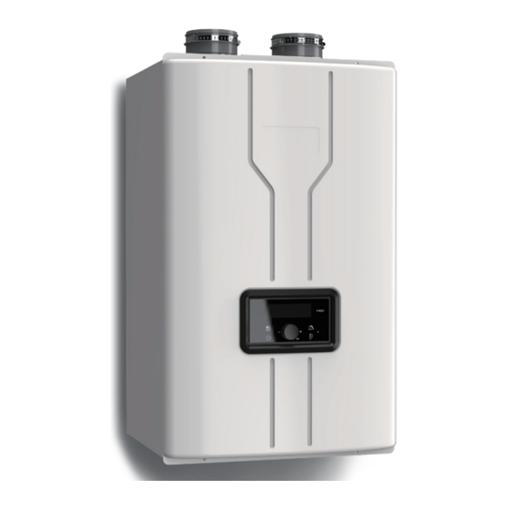
Wall-mounted, modulating gas condensing water heater
Hide thumbs
Also See for LT Series:
- Installation and operation instruction manual (98 pages) ,
- Operation instructions manual (94 pages)
Table of Contents
Advertisement
Quick Links
Installation and Operation Instructions
FOR YOUR SAFETY: This product must be installed and serviced by a professional service technician,
qualified in water heater installation and maintenance. Improper installation and/or operation could create
carbon monoxide gas in flue gases which could cause serious injury, property damage, or death. Improper
installation and/or operation will void the warranty.
If the information in this manual is not
followed exactly, a fire or explosion may
result causing property damage, personal
injury or loss of life.
Do not store or use gasoline or other
flammable vapors and liquids in the vicinity of
this or any other appliance.
WHAT TO DO IF YOU SMELL GAS
• Do not try to light any appliance.
• Do not touch any electrical switch; do not
use any phone in your building.
• Immediately call your gas supplier from a
nearby phone. Follow the gas supplier's
instructions.
• If you cannot reach your gas supplier, call
the fire department.
Installation and service must be performed
by a qualified installer, service agency, or gas
supplier.
Installation and Operation
Instructions for
LT Series
Wall-Mounted, Modulating
Gas Condensing Water Heater
Model
•
Natural Gas (NG) - Factory Configuration
•
Propane (LP) - Factory Configuration
WARNING
LT199NRX1 / LT199PRX1
(199,000 BTU/hr)
AVERTISSEMENT
Assurez-vous de bien suivres les instructions
données dans cette notice pour réduire au
minimum le risque d'incendie ou d'explosion
ou pour éviter tout dommage matériel, toute
blessure ou la mort.
Ne pas entreposer ni utiliser d'essence ou ni
d'autres vapeurs ou liquides inflammables dans
le à proximité de cet appareil ou de tout autre
appareil.
QUE FAIRE SI VOUS SENTEZ UNE ODEUR DE
• Ne pas tenter d'allumer d'appareils.
• Ne touchez à aucun interrupteur. Ne pas vous servir
des téléphones dans le bâtiment où vous vous
trovez.
• Appelez immédiatement votre fournisseur de
gaz depuis un voisin. Suivez les instructions
du fournisseur.
• Si vous ne pouvez rejoindre le fournisseur de
gaz, appelez le sservice des incendies.
L'installation et l'entretien doivent être assurés par
un installateur ou un service d'entretien qualifié
ou par le fournisseur de gaz.
Document 2192
GAZ:
Advertisement
Table of Contents

Subscribe to Our Youtube Channel
Related Manuals for Laars LT Series


Summary of Contents for Laars LT Series
- Page 1 Installation and Operation Instructions Document 2192 Installation and Operation Instructions for LT Series Wall-Mounted, Modulating Gas Condensing Water Heater Model LT199NRX1 / LT199PRX1 (199,000 BTU/hr) • Natural Gas (NG) - Factory Configuration • Propane (LP) - Factory Configuration FOR YOUR SAFETY: This product must be installed and serviced by a professional service technician, qualified in water heater installation and maintenance.
-
Page 2: Table Of Contents
Control Dial and Buttons ........46 SECTION 4 Installation LCD Overview ...........47 NOTE: For Cascading Installations, please refer Operating Mode ..........48 to document ‘Cascading the LT Series Water Status Display Mode ..........49 heater’, available online. DHW Set Point Change Mode ......50 Location and Clearances ........12 Installer Mode ............51... -
Page 3: Section 1 Product Accessories
This manual provides information necessary for the 2) CSA B149.1 "Natural Gas and Propane Installation Code" and installation, operation, and maintenance o the LT Series. with the requirement of the local utility or other authorities having All application and installation procedures must be read and jurisdiction. -
Page 4: Section 2 Product Characteristics
Page 4 SECTION 2 Product Characteristics Model Nomenclature The Model Nomenclature is shown on your Rating Plate and consists of a series of letters and numbers that further identifies the characteristics of your LT Series Water Heater. Model Size Fuel... -
Page 5: Specifications
Page 5 Specifications Model Name LT199NRX1/LT199PRX1 199,000 Btu/h Gas Input Rate 18,000 Btu/h High Elevation 180,000 Btu/h 35°F Rise 11.1 Gal/min (42 L/min) Hot Water Capacity 45°F Rise 8.7 Gal/min (32.9 L/min) 77°F Rise 5.1 Gal/min (19.3 (L/min) Installation Indoor / Outdoor Wall Hung (with outdoor vent cap) Flue System Sealed Combustion Direct Vent, Single Vent, Outdoor Max Vent Run... -
Page 6: Dimensions
Page 6 Dimensions - [LT199NRX1 / LT199PRX1] 6.9" [175mm] 5.8" [148mm] 4.6" [117mm] 17.3" [440mm] 2.4" [62mm] 3.2" [81mm] 8.9" [226mm] 6.4" [163mm] Description Size Exhaust 2" PVC Air Intake 2" PVC Hot Water 3/4" NPT Condensate 1/2" NPT Recirculation Return Connection 3/4"... -
Page 7: Names Of Components
Page 7 Names of Components [LT199NRX1 / LT199PRX1] Name of Component Name of Component Vent Pipe Collar Cold Water Inlet Combustion Air Intake Assembly Gas Inlet Main Controller Ignition Transformer Igniter Water Adjustment Valve Flame Detection Sensor Control Panel Manual Power Switch High Limit Switch Sight Glass Secondary Heat Exchanger... -
Page 8: Section 3 Safety Regulations
Page 8 SECTION 3 Safety Regulations Safety Symbols WARNING WARNING To avoid product damage, personal injury, or even FOR YOUR SAFETY READ BEFORE possible death, carefully read, understand, and OPERATING follow all the instructions in the Installation and Operation manual before installation, operation If you do not follow these instructions exactly, a fire and service the Water Heater. -
Page 9: Safety Precautions And Proper Use
Page 9 damaging condition that might affect the operation of the unit. Water Heater must be checked by a qualified technician before resuming operation. DO NOT use this Water Heater if any part has been under water. Immediately call a qualified technician for inspecting the Water Heater and replacing any part of the control system and gas control which have DANGER... - Page 10 Page 10 Safety Precautions and Proper Use When in Operation CAUTION Before Operation 1. Check the Gas Type (NG/LP) 1. Caution for Ventilation When moving the unit or setting it up for the first Ensure that there is unobstructed and sufficient inflow time, confirm that the supplied gas type (natural gas and outflow combustion air for the water heater.
- Page 11 Page 11 Gas leakage test. WARNING Gas supply line must be inspected periodically. Do not use the appliance for any other purpose than for Do not shut off the Water Heater. domestic water heating. When you leave home for a extended periods, do Do not store combustibles or flammable material such as not shut off the water heater.
-
Page 12: Section 4 Installation
Page 12 SECTION 4 Installation WARNING Location and Clearances Installations must comply with The water heater must be mounted to a suitable wall • All the local, state, provincial, and national codes, by a qualified heating contractor per the provided laws, regulations and ordinances. -
Page 13: Wall Mount Bracket
Page 13 Wall Mount Bracket 3" to Top of Unit 4.2.1 The installation height and location Anchors (4) The installation height depends on your installation scenario. With all clearances considered, and given adequate positioning Concrete, for air supply and venting, you will need to determine the Wood, best position to mount the Wall Mount Bracket. -
Page 14: Combustion Air
Page 14 SECTION 4. Installation (continued) Combustion Air LT Series water heaters must have provisions for combustion and ventilation air in accordance with the vertical or horizontal duct to the outdoors or spaces applicable requirements for Combustion Air Supply that directly communicate with the outdoors and shall... -
Page 15: Venting (Exhaust)
CAUTION II et IV doivent être pourvues de dispositifs d'évacuation du condensat. The LT Series comes from the factory set to use either Natural gas or Liquid Propane. Confirm the installation gas type matches the gas type on the Venting (Exhaust) rating plate. -
Page 16: Venting (Exhaust)
The unit must not support the weight of the vent pipe. NE PAS METTRE EN COMMUN LES UNITÉS LT AVEC UN AUTRE APPAREIL. LT Series unités ne sont jamais autorisés à partager un évent Catégorie I avec les appareils. - Page 17 Page 17 - FSA-PVC3 (3” PVC to FasNSeal UL1738 and ULCS636) Appliance Adapter) - 2 in Vent Kit #ICWT242 - FSxxxxx03 (3”) - 3 in Vent Kit #ICWT352 ● Z-Flex® Z Vent ● Z-Flex® Z DENS Horizontal Termination (Certified - 2SVSTTA023 (2” x 3” Appliance Adapter) to UL1738 and ULCS636) - 2SVEPSCF030X (Straight Pipe) - 2 in Vent Kit #2ZDHK2...
-
Page 18: General Location Guideline
Page 18 General Location Guideline 1. Vent system installation must be in accordance with Local codes or, in the absence of local codes, the National Fuel Gas Code, ANSI Z224.1 /NFPA WARNING 54 and/or CSA B149.1, Natural Gas and Propane Failure to vent this Water Heater in accordance Installation Code. -
Page 19: Locations For Vent Pipe Terminal
Page 19 Locations for Vent Pipe Terminator 4.6.1 Direct Venting Clearances U.S. Installations (see note 1) Canadian Installations (see note 2) A= Clearance above grade, veranda, porch, 12 inches (30 cm) 12 inches (30 cm) deck, or balcony See note 6 See note 6 B= Clearance to window or door that may be Direct vent only: 12 inches (30cm);... -
Page 20: Non-Direct Venting Clearances
Page 20 4.6.2 Non-Direct Venting (Single Pipe) Clearances Description US Non-Direct Canadian Non-Direct Clearance above grade, veranda, porch, deck, or balcony 12 in (30 cm) 12 in (30 cm) 48 in (120 cm) below or to side of opening; Clearance to window or door that may be opening 36 in (91 cm) 12 in (30 cm) above opening... -
Page 21: Venting Requirements In The Commonwealth Of Massachusetts
Page 21 4.6.3 Venting Requirements in the Commonwealth of Massachusetts 4. Inspection The state or local gas inspector of the In Massachusetts the following items are required if side-wall horizontally vented gas fueled appliance shall the side-wall exhaust vent termination is less than not approve the installation unless, upon inspection, seven (7) feet above finished grade in the area of the inspector observes carbon monoxide detectors and... -
Page 22: Common Vent Test
AVIS NE PAS METTRE EN COMMUN LES UNITÉS DO NOT COMMON VENT LT UNITS WITH LT AVEC UN AUTRE APPAREIL. LT Series ANY OTHER APPLIANCE. LT Series units are unités ne sont jamais autorisés à partager un évent never permitted to share a vent with Category I Catégorie I avec les appareils. -
Page 23: Air Supply And Vent Connections
Page 23 Air Supply and Vent Connections 4.7.1 Vent / Air Pipe Lengths 3˝ Combustion Air / Vent Pipe 2˝ Combustion Air / Vent Pipe Water Heater model LT199 150´ (45M) 60´ (18M) Table 6. Maximum Vent / Air Pipe Lengths for either 3" or 2 " Pipes Note : For each elbow, reduce maximum allowable length •... -
Page 24: Single Venting
Page 24 4.7.3 Single Venting Read and Follow Sections 4.3 Guidelines First. 1. Insert the termination end cap into the intake air duct. 2. Provide two openings to allow for circulation of combustion air as specified by ANSI Z224.1/NFPA 54 or CAN/CGA B-149.1: Model LT199 Maximum Input... - Page 25 Page 25 4.9 Vent Pipe Termination (cont) Horizontal Vent Termination • Direct Vent - Sidewall Termination Exterior Wall Vent Screens are required 1” MIN Exhaust Elbow 12” MIN 12” MIN Exhaust Apart Exhaust Screen NOTE: The Exhaust must Air Intake Screen NOTE: Must be 12”...
- Page 26 Page 26 • Direct Vent - Optional Side wall Terminations Exterior Wall Concentric Vent Termination • Direct Vent - Optional Horizontal Exterior Wall Side Wall Kit and Vertical Concentric Vent (2” or 3”) Side Wall Kit Exhaust (2” or 3”) 12”...
-
Page 27: Gas Supply And Piping
Verify that the appliance is fitted for the proper type appliances sharing the gas supply line must be firing at of gas by checking the rating plate. LT Series water maximum capacity to properly measure the inlet supply heaters will function properly at elevations up to pressure. - Page 28 Page 28 4.9 Gas Supply and Piping (continued) The gas connection fitting on the unit is 3/4˝ male To facilitate any future maintenance, it is also NPT. recommended that an approved gas union fitting be installed in the supply line between the shut-off valve The supply line must be sized for the maximum and the 3/4˝...
- Page 29 Page 29 Natural Gas piping installation. The Water Heater is The Water Heater is recommended to be recommended to be the first appliance to the first appliance to be connected to the be connected to the gas supply line. gas supply line. Union Other applianc Connection...
-
Page 30: Gas Supply Pressure
Page 30 4.10 Gas Supply Pressure Refer to the illustration. Check the gas inlet pressure measurement from inlet gas pressure port.(Loosen the port bolts before you check the gas inlet pressure.) 1. The appliance and its individual shutoff valve must Offset Fire be disconnected from the gas supply piping system during any pressure testing of that system at test... -
Page 31: Gas High Altitude Setting
4.12 Gas High Altitude Setting (no adjustment is needed below 2000 feet) The LT Series has been set up at the factory for altitudes of less than 2,000 ft, but it may be installed at elevations up to 10,000 ft for use with Natural Gas or Propane. If the... -
Page 32: Plumbing Guidelines
Page 32 4.13 Plumbing Guidelines. - Ensure pipe material is suitable for the local codes and industry standards. - The pipe must be cleaned and without any debris. - Do not apply torch heat within 12˝ of the bottom connections of the unit. - The size of the hot water pipe should be 3/4˝... -
Page 33: Re-Circulation Setting
Page 33 4.14 Re-Circulation Setting Select Water Heater Mode (LT199NRX1, LT199PRX1) Setting Requirement Performance Mode Description Dedicated Wait Time Energy Hot Water 11:RC Accessory Return Line Water Savings Savings Temperature No Recirculation Same as regular tankless water heaters. Internal Hot water without dedicated return line. Itnl Better Better... - Page 34 Page 34 Recirculation Mode [ External Mode] · Provides most comfortable option. Maintains consistent hot water availability during specified times. · Timer can be manually customized or programmed to automatically learn daily usage patterns. · Ability to optimize by using Installer Mode function 3: RT to adjust loop temperature for maximum comfort and safety.
- Page 35 Page 35 Recirculation Mode [ On Demand(tt24) Mode] · Provides best energy savings option · Designed to meet California Title 24 requirements. · Recirculation will only operate when the push button switch is pressed. Hot water will not be available immediately.
- Page 36 Page 36 Recirculation Mode [ Crossover(CrOS) Mode] · Provides recirculation option for homes without a dedicated return line by utilizing the cold water line as a return line. · Timer can be manually customized or programmed to automatically learn daily usage patterns. ·...
-
Page 37: Setting The Control Panel
Page 37 4.15 Setting the Control Panel Setting the internal Clock ►To use the ‘Recirculation Timer’, the device’s internal clock should be adjusted to the current time. Clock settings can be set in the ‘User Mode’. [ To enter ‘User Mode’ ] [A:GA] is displayed on the display screen. - Page 38 Page 38 To set the recirculation mode (Internal, External, On-Demand, Crossover) 1. Press the 'Power Button' OFF. ('Display Screen' will be blank) 2. Press and hold the ‘Function Button’ for approximately 5 seconds to get into the ‘Installer Mode’. 3. ‘1:EH’ oFF will appear on the ‘Display Screen’. Rotate the dial clockwise until ‘11:RC’...
-
Page 39: Disposal Of Condensate
Page 39 4.16 Disposal of Condensate High efficiency gas condensing Water Heaters create condensation when operating. Condensation has acidic (pH) of approximately 4-5. Condensate must be drained in accordance with all local regulations. Follow your local code with regards to the disposal of condensation. One of 3 disposal methods must be followed 1. -
Page 40: Pressure Relief Valve
Page 40 4.17 Pressure Relief Valve WARNING An approved ‘Pressure Relief Valve’ must be installed in this installation. The Valve must be an approved ASME HV Relief Valve, installed on the DHW supply line for domestic hot water loop as close to the unit as possible. (Valve size 3/4˝, maximum 150psi). -
Page 41: Dip Switches
Page 41 4.19 DIP Switches There is one set of DIP switches. DIP switches 6 and 7 must be set to OFF when operating the water heater normally. DIP Switch Function Machine power Do NOT Move. OVER-RIDE Inlet DHW Flow Limiter Propane or Natural Gas Max. -
Page 42: Wiring Diagram
Page 42 4.20 Wiring Diagram... -
Page 43: Ladder Diagram
Page 43 4.21 Ladder Diagram... -
Page 44: Electrical Connections
Page 44 4.22 Electrical Connections Connector Descriptions SELV no. of location and type Pin nr. Board Silk GROUND Power Supply Line Internal Circulation Pump Ignition Transformer HEAT/CP2 Ceramic Heaters HT (120V~) Gas Valve Unuse Power Supply Neutral 9-12 AC Power COM Line RS485 + RS485 - RS-485... - Page 45 Page 45 Connector Description SELV no. of location and type Pin nr. Board Silk Flame Sensor OP.S Outlet Operating Water Temperature Sensor 3,10 DH.S DHW Temperature Sensor 4,11 Inlet Water Temperature Sensor SELV (5V) 5,12 BG.S Exhaust Water Temperature Sensor 6,13 ST.S Surface Temperature Sensor...
-
Page 46: Section 5 Control Display And Operation
Page 46 SECTION 5 Control Display and Operation Control Dial and Buttons Indicator (Green) Function Button Hot Water Temperature Button Display Screen Power ON / OFF Button Dial Button / Enter Button Recirculation Timer For turning the water heater ON / OFF. Functionalities Buttons PRESS (Tap) -
Page 47: Lcd Overview
Page 47 LCD Overview LCD has a backlight that will illuminate: • When a user action is detected (a button is pressed) • Turns off when no action within approximately 20 seconds. Combustion Icon PCB-Display Connection Status External Recirculation Icon Temperature Unit Hot Water Operating Icon Lock Mode... -
Page 48: Operating Mode
Page 48 Operating Mode Operating Mode After the Power is turned on, and/or the Control Display is turned on , the Control Display will go through a ‘Start Up’ checklist and briefly show a sequence of diagnostic codes before entering into the ‘Operating Mode. It will then display the following information. Indicate Example Target DHW Temperature... -
Page 49: Status Display Mode
Page 49 Status Display Mode Index Description Main HotF DHW flow rate by On demand A:GA rCLF Circulated water flow rate by Internal pump b:Fr Current Blower rpm C:oP Heat Exchanger temperature D:dH DHW Hot outlet temperature E:Eh Exhaust gas temperature F:In Cold Inlet temperature Power Supply Time : 0000 hours... -
Page 50: Dhw Set Point Change Mode
Page 50 DHW Set Point Change Mode The LT Series has a built in water flow limiter and will automatically adjust the flow rate up or down based on outlet temperature at the inlet side of the water heater. If... -
Page 51: Installer Mode
Page 51 Installer Mode These changes are to be made only by a qualified technician. To c hange any of the Installer Parameters, Start by turning OFF the Power to the Display Control. Then, with the power OFF, press and HOLD (5 seconds) the button to get into the installer mode. -
Page 52: Error Mode
Page 52 Error Mode Flashing Indicate Example Error ‘Er . xx’ will flash Installer icon NOTE: When communication between the Control Display and the main controller is lost, the will not be displayed. -
Page 53: Section 6 Error Codes
Page 53 SECTION 6 Error Codes Error Codes Error *Lockout Error Code Description Possible Remedies Code Type Press the Power button to clear the Error Code. If Error happens again: 1. Monitor the gas pressure to the water heater while in operation. Ensure pressure is between 3.5 and 14"WC. - Page 54 Page 54 6.1 Error Codes (continued) Error *Lockout Error Code Description Possible Remedies Code Type This Error Code will clear when the false flame condition is remedied. If Error happens again: Flame Detected after 1. Check the water heater cover. Ensure it is secure. Flame detection sensor can detect an external Exiting a Flame On light source.
- Page 55 Page 55 6.1 Error Codes (continued) Error *Lockout Error Code Description Possible Remedies Code Type "Press the Power button to clear the Error Code 1. Check if dip switch MAX Fire setting is ON. Switches 6 and 7 should be OFF for normal operation. 2.
- Page 56 Page 56 6.1 Error Codes (continued) Error *Lockout Error Code Description Possible Remedies Code Type This Error Code will clear when the condition is remedied. If Error happens again: Poor Communication Soft Lock 1. Check connections from main control to display panel. 2.
-
Page 57: Section 7 Troubleshooting
Page 57 SECTION 7 Troubleshooting Diagnostics Before calling for service, review the following diagnostic steps first for saving time and money. Question & Answer Indicate Indicator Make sure that the ON/OFF button on the Control Panel has been turned ON. If the monitor on the Control Panel is blank, make sure the power cord is plugged and fuses on the main controller in the units are good. - Page 58 Page 58 7.1 Diagnostics (continued) Diagnostics and suggested corrective actions This controller is able to record information about the water heater’s condition for the ten previous faults or errors. Refer to the ‘Error Code’ section of this Manual, (Section 6). Display Condition Diagnostic...
- Page 59 Page 59 Display Condition Diagnostic Corrective Action(s) Burner may be operating too hot due to incorrect combustion. Occurs when flame Reset using manual switch. is detected when Reset screen on control Check for flame at burner via flame current with FLAME FAULT there should be no panel.
-
Page 60: Section 8 Maintenance
Page 60 SECTION 8 Maintenance Annual Startup and General Maintenance Regular Maintenance - Check power source. After the water heater installation is completed, this Make sure that the power cord is correctly connected. manual should be placed in safe dry location near The main power line is connected to the manual the water heater. - Page 61 Page 61 - Cleaning Air Intake Filter - To properly maintain the water heater, you should clean the air intake filter every 3 months. If not, you may encounter combustion issues To clean air intake filter: 1. Press Power button on the control panel to turn off the water heater. 2.
- Page 62 Page 62 8.1 Annual Startup and General Maintenance (continued) - Flushing the Water Heater 8. Disconnect all hoses. 9. Remove the cold water inlet filter from the water heater Flushing the Heat Exchanger of the water heater is and clean out any residues. a complicated procedure and should only be done 10.
-
Page 63: Section 9 Installation Check
Page 63 SECTION 9 Installation Check Quick View Final check lists Before Installing Final check: Installation Conditions. - Make sure that there is enough space for installing • Is the Water Heater properly mounted on the wall? • Is there space for a drain which is close to the water and gas line. -
Page 64: Final Check Lists
Page 64 Final Check List (continued) Final check : Connecting the power supply • Check that the power is 120V AC. • Confirm the polarity of the electrical connection. Final check : Pressure relief valve • Have you installed an approved pressure relief valve on the water heater? •... -
Page 65: Section 10 Lt Series Warranty
SECTION 10 LT Series Warranty LAARS HEATING SYSTEMS COMPANY L I M I T E D L T S E R I E S T A N K L E S S W A T E R H E A T E R W A R R A N T Y... - Page 66 HOW DO YOU GET WARRANTY ASSISTANCE? Upon discovering a defect or problem, you should: 1. Contact either the Installer or dealer, or 2. Contact us-- LAARS HEATING SYSTEMS COMPANY CUSTOMER SERVICE AND PRODUCT SUPPORT 20 INDUSTRIAL WAY ROCHESTER, NH 03867 1.800.900.9276...
- Page 67 Customer Service and Product Support: Industrial Way, Rochester, NH, USA 03867 • 603.335.6300 • Fax 603.335.3355 Headquarters: 9 Brigden Gate, Halton Hills, Ontario, Canada L7G 0A3 (905) 203-0600 Fax: (905) 636-0666 www.Laars.com Litho in U.S.A. © Laars Heating Systems 22-07 Document 2192...
- Page 68 Customer Service and Product Support: Industrial Way, Rochester, NH, USA 03867 • 603.335.6300 • Fax 603.335.3355 Headquarters: 9 Brigden Gate, Halton Hills, Ontario, Canada L7G 0A3 (905) 203-0600 Fax: (905) 636-0666 www.Laars.com Litho in U.S.A. © Laars Heating Systems 22-07 Document 2192...
Need help?
Do you have a question about the LT Series and is the answer not in the manual?
Questions and answers