Sign In
Upload
Download
Table of Contents
Contents
Add to my manuals
Delete from my manuals
Share
URL of this page:
HTML Link:
Bookmark this page
Add
Manual will be automatically added to "My Manuals"
Print this page
×
Bookmark added
×
Added to my manuals
Manuals
Brands
ABB Manuals
Control Panel
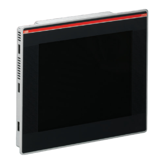
CP660-x
Operating instructions manual
ABB VICPAS CP660-x Operating Instructions Manual
Hide thumbs
Also See for VICPAS CP660-x
:
Operating instructions manual
(27 pages)
1
Table Of Contents
2
3
4
5
6
7
8
9
10
11
12
13
14
15
16
17
18
19
20
21
22
23
24
25
26
27
28
page
of
28
Go
/
28
Contents
Table of Contents
Bookmarks
Table of Contents
Table of Contents
Introduction
Before You Start
Safety Notices
Markups
Product Overview
Standards and Approvals
Product Identification
Technical Specifications
Environmental Conditions
Electromagnetic Compatibility (EMC)
Durability Information
Technical Data
Dimensions
Installation Environment
Applying the Rectangular Gasket
Installation Procedure
Connections
Serial Ports
Ethernet Port
Power Supply, Grounding and Shielding
AUX Port
Battery
Cleaning Faceplates
Getting Started
Advertisement
Quick Links
Download this manual
Operating Instructions
Control Panels CP600
CP650-x, CP650-WEB-x
CP660-x, CP660-WEB-x
CP675-x, CP675-WEB-x
Table of
Contents
Previous
Page
Next
Page
1
2
3
4
5
Advertisement
Table of Contents
Need help?
Do you have a question about the VICPAS CP660-x and is the answer not in the manual?
Ask a question
Questions and answers
Subscribe to Our Youtube Channel
Related Manuals for ABB VICPAS CP660-x
Control Panel ABB CP650-x Operating Instructions Manual
Cp600 series (27 pages)
Industrial Equipment ABB AC500 V3 System Manual
Automation builder, programmable logic controllers, control panels (119 pages)
Control Panel ABB CP 600 Series Operating Instructions Manual
(29 pages)
Control Panel ABB CP600 Series Operating Instruction
(24 pages)
Control Panel ABB CP600 Operating Instructions Manual
Control panels with microbrowser (24 pages)
Control Panel ABB CP635-WEB Operating Instructions Manual
Control panels with microbrowser (24 pages)
Control Panel ABB CP6 WEB Series Start-Up Instructions
(2 pages)
Control Panel ABB CP600-eCo Operating Instruction
(26 pages)
Control Panel ABB CP604 Operating Instruction
(26 pages)
Control Panel ABB CP607 Operating Instruction
(26 pages)
Control Panel ABB CP607-B Operating Instruction
(26 pages)
Control Panel ABB CP6407 Operating Instruction
(24 pages)
Control Panel ABB CP6410 Operating Instruction
(24 pages)
Control Panel ABB CP6415 Operating Instruction
(24 pages)
Control Panel ABB CP600-WEB Application Note
Microbrowser (9 pages)
Control Panel ABB CP600-Pro Quick Start Manual
(7 pages)
This manual is also suitable for:
Vicpas cp650-x
Vicpas cp600 series
Vicpas cp675-x
Vicpas cp650-web-x
Vicpas cp660-web-x
Vicpas cp675-web-x
...
Show all
Vicpas cp650
1sap550100r0001
Table of Contents
Print
Rename the bookmark
Delete bookmark?
Delete from my manuals?
Login
Sign In
OR
Sign in with Facebook
Sign in with Google
Upload manual
Upload from disk
Upload from URL


Need help?
Do you have a question about the VICPAS CP660-x and is the answer not in the manual?
Questions and answers