
Subscribe to Our Youtube Channel
Related Manuals for AEROCOMPACT CompactGROUND GS10plus


Summary of Contents for AEROCOMPACT CompactGROUND GS10plus
- Page 1 CompactGROUND GS10plus Assembly Instructions Version: 01 Language: English | Original language: German Original installation instructions Important! Read carefully before installation!
- Page 2 The original language of these assembly instructions is German. Any assembly instructions in another lan- guage are a translation of the assembly instructions in German. The assembly instructions are protected by copyright. Without written permission from AEROCOMPACT® the assembly instructions may not be copied, reproduced, microfilmed, translated or converted for storage and processing in computer systems, either in part or in full.
-
Page 3: Table Of Contents
Version 3: Long ballast tray Install cable pipes (optional) Installing the cable pipe to the ballast tray Fasten the cable pipes with brackets Grounding Install grounding / bonding equipment (not USA-compliant) Install grounding / bonding equipment (USA-compliant) Maintenance Complete System Fittings www.aerocompact.com... - Page 4 Dismantling Disassemble components www.aerocompact.com...
-
Page 5: About This Document
Symbols in Illustrations Activities Certain activities are required to carry out the assembly. These activities are shown in the illustrations with the following symbols. Check AEROTOOL planning documents Visual inspection Activity by hand Observe right angle Optional component, optional installation method www.aerocompact.com... -
Page 6: Target Group
PV modules used with the CompactGROUND GS system should be approved by the module manufacturer. AEROCOMPACT accepts no liability for loss of performance or damage of any kind to the PV modules. Any other use of the CompactGROUND GS system is considered improper. -
Page 7: Guarantee
We would like to point out that the flat roof system is being sold as part of a sales contract. Assembly/- processing by the purchaser or third parties is not carried out on behalf of or for Aerocompact and must be carried out by qualified personnel strictly in accordance with the assembly instructions. - Page 8 About This Document www.aerocompact.com...
-
Page 9: Safety
Never work in wet conditions or at temperatures below the freezing point. Depending on the roof pitch there is a risk of slipping. Dangers from the environment Keep sufficient distance from overhead electrical lines. The following distances must be observed: www.aerocompact.com... -
Page 10: Protection Against Falling Objects
Personal protective equipment is required to prevent injuries during assembly work. Wear protective goggles when drilling. Wear safety boots. Wear cut-resistant work gloves during assembly. Helmets are required for all persons involved on the construction site. Use fall protection. www.aerocompact.com... -
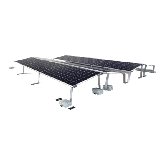
Page 11: System Overview
Basic components GS10plus End clamp, varying clamp height for 30 - 50 mm frame heights | CLEG10-XX Connector bracket | GS10+CN Middle bracket | GS10+MB Front bracket | GS10+FB Mid clamp, for 30 - 50 mm frame heights | CLMG10 www.aerocompact.com... -
Page 12: Ballasting
Tapping combi screw M8x20 | SCS8x20 Accessories Cable conduit | CP-430, CP-620, CP-840 Bracket for cable conduit | BR-CP Roof protection pad 290 x 100 x 3.8 | PP290/100 Cable Tie Clip for Module Frame | CLP-M Accessories for grounding / potential equalization (USA) www.aerocompact.com... - Page 13 System Overview Grounding lug with nut (follows UL 476 or UL 2703 requirements) | GL18N www.aerocompact.com...
-
Page 14: Assembly
For the bracket, make sure that the roof protection pad covers the edge in each case: A = 10 mm. Depending on the design of the connector bracket, attach 1 to 2 roof protection pads. www.aerocompact.com... -
Page 15: Pre-Install The Clamps
Assembly Remove protective paper. Attach adhesive surface to the underside of the bracket. Pre-install the clamps Pre-install the end-clamps or mid-clamps to the front brackets, middle brackets and connector brackets as needed. www.aerocompact.com... -
Page 16: Measure Area, Place Components
Place the front brackets, middle brackets and connector brackets in the array field Edge rows: place front brackets, middle brackets and connector brackets with end-clamps pre-installed. Middle rows: place front brackets, middle brackets and connector brackets with mid-clamps pre-installed. www.aerocompact.com... -
Page 17: Installing The Modules
The distance between the clamps is determined by the brackets and connector brackets or by the mod- ule size. Install the first module row Weigh down the front brackets with ballast blocks Place the module on the front brackets and middle brackets. www.aerocompact.com... - Page 18 20 Nm or 14.75 ft lbs. Tighten the screws of the end clamps at the bottom of the modules to 20 Nm or 14.75 ft lbs. Mount modules of the first row until row is finished. www.aerocompact.com...
-
Page 19: Install The Second Module Row
Tighten the screws of the end clamps with 20 Nm or 14.75 ft lbs. Install remaining modules as in the first row. Install other modules in the recommended order. Tighten all end clamps and mid clamps to 20 Nm or 14.75 ft lbs. www.aerocompact.com... -
Page 20: Place Ballast
The short ballast tray can be installed in the following positions: at the front bracket. on the connector bracket. at the end bracket - last row - mirror of front bracket. Refer to the Aerotool planning documents for the exact number and position of the short ballast trays. www.aerocompact.com... -
Page 21: Version 3: Long Ballast Tray
The long ballast tray can be installed in the following positions: across the front bracket. underneath the middle bracket. on the connector bracket. across the end bracket (last row, mirror of front bracket). Refer to the Aerotool planning documents for the exact number and location of long ballast trays. www.aerocompact.com... -
Page 22: Install Cable Pipes (Optional)
Screw the ballast tray to each middle bracket with 2 tapping combi screws Tighten the screws with 15 Nm or 11 ft lb. Install cable pipes (optional) The cable pipes can be installed at the edges of the module field. www.aerocompact.com... -
Page 23: Installing The Cable Pipe To The Ballast Tray
Screw the brackets for cable pipe to the connector bracket or to the middle bracket each with a tap- ping combi screw. Tighten the screws with 15 Nm or 11 ft lb. Grounding www.aerocompact.com... -
Page 24: Install Grounding / Bonding Equipment (Not Usa-Compliant)
Attach washer and cable lug in the order shown with the screw Tighten the screw Install grounding / bonding equipment (USA-compliant) The grounding / potential equalization is mounted at the edge of a module field on a bracket. www.aerocompact.com... - Page 25 Attach an appropriately sized copper grounding wire (provided by customer) to the grounding lug with the screw Potential equalization during maintenance Attention! If a module is removed, attach additional ground clamps and ground wire to ensure connection between modules and equipotential bonding. www.aerocompact.com...
-
Page 26: Maintenance
Complete System Check all components of the system for damage. Replace damaged components as soon as possible. Fittings Check all screw connections. Tighten loose screw connections. Confirm the tightening torque according to the assembly instructions. www.aerocompact.com... - Page 27 Dismantling DISMANTLING Disassemble components Disassembling the system: Carry out the assembly steps in reverse order. www.aerocompact.com...
Need help?
Do you have a question about the CompactGROUND GS10plus and is the answer not in the manual?
Questions and answers