Table of Contents
Advertisement
Quick Links
Advertisement
Table of Contents

Related Manuals for AEROCOMPACT S5


Summary of Contents for AEROCOMPACT S5
- Page 1 INSTALLATION MANUAL AEROCOMPACT S 5°/10°/15°...
- Page 3 A list of PV modules with proven compliance in terms of UL 1703 pany AEROCOMPACT is not liable for damages occurring from is being built up by and can be obtained from Aerocompact upon request. non-compliance with the installation instructions, particularly the safety instructions, as well as from misuse of the products.
- Page 4 TUV certified, conforms to IEC 61215 > Class A fire rated acc. to ANSI/UL 1703 when equipped with side deflectors (tested with the S5 racking type, to be con- firmed for S10, S15, and + systems). > Best price value available >...
- Page 5 New System Update NEW module-clamp incl. grounding-pins, TUV certified to UL2703 NEW cable management solution NEW fleece building protection mat certified and long-term tested...
-
Page 6: Technical Details
AEROCOMPACT S 10 (25°): 15 inch (380 mm) AEROCOMPACT S 15 (25°): 22.5 inch (571 mm) Min. Array Size: AEROCOMPACT S: 2 rows with 3 modules / 3 rows with 2 modules Roof Edge Zone: Roof areas F and G can be used Module Dimensions: 37.4–41.3 inch x 61.1–81.9 inch (width –... - Page 7 S5 18° Sun-angle S5 30° Sun-angle S10 18° Sun-angle S10 25° Sun-angle S15 18° Sun-angle S15 25° Sun-angle...
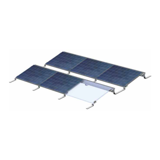
- Page 8 The installation system AEROCOMPACT S is a robust racking system for mounting PV modules on flat roofs. It consists of If you have any other questions, make use of AEROCOMPACT’s prefabricated aluminum retaining brackets with glued on building professional and comprehensive consulting service. Our engi- protection pads, deflector plates and all required small parts...
-
Page 9: Safety Information
SAFETY INFORMATION It is important that you install person-independent The manufacturer hereby agrees to take back for fall arrest systems or reception system according recycling all products that are marked with the to Norm in your Country prior to the start of work! eco-label as well as all materials used herein. -
Page 10: Scope Of Delivery
SCOPE OF DELIVERY Front Bracket End Bracket Connector Windsheet Ballast Tray Ballast Tray Long End Clamp Middle Clamp Socket Screw M8x30 Washer Cable-Tie incl. Clips function Clips for Windsheet Revet Nut M8 Flathead Screw Allenhead Nut Alpine back Bracket Alpine front Bracket Protection Pad Ballast Block (not included in delivery) -
Page 11: System Overview
M8 Screw Ballast Block 16 x 8 x 2 inch END CLAMP Rivet NUT M8 Rivet Nut M8 Aerocompact PROTECTION PAD Aerocompact FRONT SUPPORT BRACKET BACK SUPPORT BRACKET optional (high snow load) optional (high snow load) Snowload > 2,4 kN... - Page 12 INSTALLATION MANUAL Attach the end and middle clamps to the Aerocompact Brackets. Measure the starting point Use chalk line marking Place Front Bracket Attach protection pads to ballast block (Aerocompact recommends glueing, see p. 22) Secure front bracket with ballast block...
- Page 13 Place the Connector vertically with spacing (module width). The exact distance is adjusted during module assembly. Module width Place the Connector with spacing (module length) in horizontal position. The exact distance is adjusted during module assembly. Module length...
- Page 14 Mount the module in landscape orientation on the mounting brack- ets and align flush above the back of the AEROCOMPACT connec- tor or end bracket. (NOTE: does not apply to S5/30° system, see p. 22 for use of the spacer bracket)
- Page 15 INSTALLATION of Alpine Version For snow load of more than 50 psf (design load) additional support brackets must be installed on the lower and upper end centered of the module. Place the front support bracket (after pre-assembling an end clamp on top) on the lower module end centered in the middle and tighten.
- Page 16 Fixation of windsheet to bracket The windsheet of the S5 systems has a symmetrical cross section, and thus no “wing tip”. Install it in a way that the slotted holes are close to the upper edge and the rounded holes are close to the lower edge.
- Page 17 5 ballast blocks can be installed in the Protection Pads front ballast tray. Attach protection pads to each ballast tray (Aerocompact recommends glueing, see p.22). The standard (short) tray requires 2 pads (left and right end), the long tray requires 4 pads (evenly distributed over the tray length).
- Page 18 The tray is bolted additionally in the center of the windsheet using a cage nut, allen-head screw and washer. NOTE In case of the S5 systems, wind sheets are left out where long ballast trays, running over the whole length of the module, are present (see p.22).
- Page 19 According to VDE 0185-305-3 supplement 5 to the install grounding wires between the separation distance between the PV system and the lightning protection system modules. must be observed. AEROCOMPACT is not liable for damages that may result from lightning strikes or grounding issues.
-
Page 20: Bonding And Grounding
Continuous bonding between modules and the mounting system, and thus between all module frames and racking elements within an array, is achieved by Aerocompact‘s module clamps with intergrated pins. The performance of these clamps has been tested and recognized for UL listing. - Page 21 This racking system may be used to ground a PV module complying with UL 1703 only when specific module has been evaluated for grounding in compliance with included instructions. A list of PV modules with proven compliance in terms of UL 1703 is being built up and can be obtained from Aerocompact upon request.
- Page 22 Windsheet installation with the S5 system The windsheet of the S5 system (both sun angles) has to be installed in a way that the slotted holes are located along the upper edge and the rounded holes along the lower edge (see picture below).
- Page 23 Example of module manufacturer’s approval for short side clamping with/without center support A rooftop PV system imposes additional load onto the roof. For Aerocompact flat roof sys- tems, the design software calculates this additional load in terms of the absolute load (in lb) for an entire roof, as a surface-related average load (in psf), as well as reduced to a point load (in lb) under each individual support element.
- Page 24 Aerocompact cable management The UL certified cable management solution is designed for the string cable management (home runs) between the mod- ule rows. For the ultimate cable management please use certified cable trays according to the national regulations. ATTENTION Tighten the bracket with the M8x30 allen head screw also used for the winddeflector.
- Page 25 Mounting bracket for micro inverter and optimizer To fix a micro inverter or optimizer use the UL certified mounting bracket specially designed for the Aerocompact Connector. Article-no. 823019...
- Page 26 Installation of the penetration points If the maximum allowed roof weight is exceeded due to PV system, Aerocompact provides a Hybrid solution. This com- bination of penetration points and ballast reduces the overall weight of the system. Furthermore, this option is used in areas with seismic activity to prevent movement of the system due to vibrations from earthquakes.
- Page 27 After finishing the installation, attach a type label to the racking system. Name /Norm: Aerocompact Inc., North Carolina It is provided by Aerocompact and presents essential data on the manufac- Aerocompact Trademark / Marque Deposée: turer, type, date of manufacturing, load rating, and fire rating of the mounting...
-
Page 28: Safety Information And Warnings
We require that the used roof insulation can hold the point load The contractor must ensure that contracted persons are of Aerocompact system and recommend the use of a insulation able to judge the tasks assigned to them and recognize any with a high load capacity of the Type DAA-ds according to DIN potential dangers. -
Page 29: Important Notes
> As an installer, you are responsible for the precise execution of DIN VDE 0100 (Installation of high voltage systems with the installation. AEROCOMPACT is not liable for the size informa- nominal voltages up to 1000 V) > tion contained in the system offers. -
Page 30: Important Warnings
IMPORTANT NOTES Important warnings Maintenance PV installations should be checked at least annually, plus af- Solar modules produce electricity as soon as they are subjected to light and are always energised. Although touch protection ter extreme weather events (high snow load, heavy storms). is provided in the form of the fully insulated plug contacts, For the racking system the following items are rmost elevant: you must take be aware of the following when handling solar... -
Page 31: Product Liability
Technical documentation is part of the project to be supplied. before the installation starts, that the product meets the AEROCOMPACT accepts no responsibility for damage incurred static requirements on site according to DIN EN 1991 as a result of noncompliance with the installation instructions or >... - Page 32 The Aerocompact S 5°/10°/15° systems may be used to ground and/or mount PV The Aerocompact S 5°/10°/15° systems may be used to ground and/or mount PV modules complying modules complying with UL 1703 only when the specific module has been...
- Page 33 A-6822 Satteins Austria / Europe Phone. 480 432 3900 Toll free. 800 578 0474 Phone. +43 (0)5524 225 66 E-mail. office@aerocompact.com E-Mail. office@aerocompact.com Web. www.aerocompact.com Web. www.aerocompact.com Sales Office California Engineering Office Germany Sales Office Hungary 55 New Montgomery Str. Suite 624 Sasbacher Str.
Need help?
Do you have a question about the S5 and is the answer not in the manual?
Questions and answers