Table of Contents
Advertisement
Quick Links
NF325-A9
FCC Information and Copyright
This equipment has been tes ted and found to comply with the limits of a Class
B digital devic e, purs uant to Part 15 of the FCC Rules . T hese limits are designed
to provide reasonable protec tion against harmful interference in a residential
installation. T his equipment generates , uses and can radiate radio frequency
energy and, if not ins talled and used in accordance with the instructions , may
cause harmful interference to radio communications . There is no guarantee
that interference will not occur in a particular ins tallation.
The vendor makes no representations or warranties with respec t to the
contents here and s pecially disclaims any implied warranties of merchantability
or fitness for any purpose. Further the vendor reserves the right to revise this
publication and to make c hanges to the c ontents here without obligation to
notify any party beforehand.
D uplication of this publication, in part or in whole, is not allowed without first
obtaining the vendor's approval in writing.
The content of this user's manual is subject to be c hanged without notice and
we will not be res ponsible for any mis takes found in this user's manual. All the
brand and produc t names are trademarks of their respec tive companies .
i
Advertisement
Chapters
Table of Contents

Related Manuals for Biostar NF325-A9


Summary of Contents for Biostar NF325-A9
- Page 1 NF325-A9 FCC Information and Copyright This equipment has been tes ted and found to comply with the limits of a Class B digital devic e, purs uant to Part 15 of the FCC Rules . T hese limits are designed to provide reasonable protec tion against harmful interference in a residential installation.
-
Page 2: Table Of Contents
Table of Contents Chapter 1: Introduction ..............1 Motherboard Features............. 1 Package Checklist ............5 Layout and Components..........6 Chapter 2: Hardware Installation ..........7 Installing Central Processing Unit (CPU)......7 FAN Headers ..............8 Installing System Memory..........9 Connectors and Slots............. 10 Chapter 3: Headers &... -
Page 3: Chapter 1: Introduction
NF325-A9 CHAPTER 1: INTRODUCTION OTHERBOARD EATURES A. Hardware Supports Socket 939. Supports AMD Athlon 64 FX/ Athlon 64 processo r. Supports AMD Sempron processo r. AMD 64 architecture enables simultaneous 32 and 64 bit computing. Supports HyperTransport Technology up to 1000MHz Full duplex. - Page 4 NF325-A9 On Board IDE Supports 4 IDE disk drives. Supports PIO mode 0~4, Block Mode and Ultra DMA 33/66/100/133 bus master mode. Slots Five 32-bit PCI bus master slots. One AGP 8x slot System Memory Supports Dual Channel DDR-333/400. Supports 8 banks in total.
- Page 5 NF325-A9 On Board AC’97 Sound Code c Chip: ALC655. Compliant with AC’97 version 2.3 specification. Supports 6 channels. Se rial ATA Supports 2 serial ATA (SATA) ports. Compliant with SATA 1.0 specification. Data transfer rates up to 1.5Gb/s. 10/100 LAN PHY: RTL8201BL Supports 10 Mb/s and 100 Mb/s auto-negotiation.
- Page 6 NF325-A9 1 Floppy connector supports 2 FDD with 360K, 720K, 1.2M, 1.44M and 2.88Mbytes. 2 IDE connectors support 4 hard disk devices. 2 Serial ATA connectors support 2 SATA devices. 2 USB headers support 4 USB 2.0 ports at front panel.
-
Page 7: Package Checklist
NF325-A9 ACKAGE HECKLIST FDD Cable X 1 HDD Cable X 1 User’s Manual X 1 Fully Setup Driver CD X 1 Rear I/O Panel for ATX Case X 1 USB 2.0 Cable X1 (optional) S/PDIF Cable X 1 (optional) Serial ATA Cable X 1 (optional) -
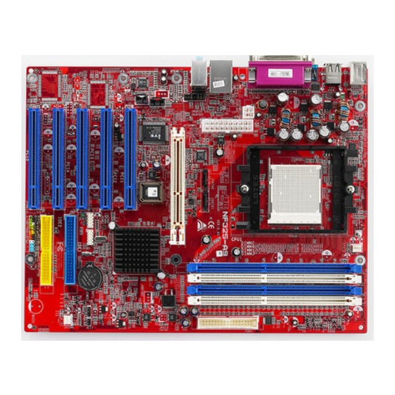
Page 8: Layout And Components
NF325-A9 AYOUT AND OMPONENTS JCFAN1 10 /100 JATXPWR1 (o pti o nal ) AGP1 JSPDI F_ IN JCDIN1 ( op tiona l) BI OS Co de c JSPDIF _OUT Giga LAN (op tion al) BAT1 IDE1 JSFAN 1 I E EE 139 4... -
Page 9: Chapter 2: Hardware Installation
NF325-A9 CHAPTER 2: HARDWARE INSTALLATION (CPU) NSTALLING ENTRAL ROCESSING CPU1 Step 1: Remove the socket protection cap. Step 2: Pull the lever toward direction A from the socket and then raise the lever up to a 90-degree angle. Step 3: Look for the white triangle on socket, and the gold triangle on CPU should point forwards this white triangle. -
Page 10: Fan Headers
NF325-A9 Step 4: Hold the CPU down firmly, and then close the lever toward direct B to complete the installation. Step 5: Put the CPU Fan on the CPU and buckle it. Connect the CPU FAN power cable to the JCFAN1. This completes the installation. -
Page 11: Installing System Memory
NF325-A9 NSTALLING YSTEM EMORY 1. Unlock a DIMM slot by pressing the retaining clips outward. Align a DIMM on the slot such that the notch on the DIMM matches the break on the Slot. 2. Insert the DIMM vertically and firmly into the slot until the retaining... -
Page 12: Connectors And Slots
NF325-A9 ONNECTORS AND LOTS FDD1: Floppy Disk Connector The motherboard provides a standard floppy disk connector that supports 360K, 720K, 1.2M, 1.44M and 2.88M floppy disk types. This connector supports the provided floppy drive ribbon cables. IDE1/IDE2: Hard Disk Connector... - Page 13 NF325-A9 PCI1~PCI5: Peripheral Component Interconnect Slots This motherboard is equipped with 5 standard PCI slots. PCI stands for Peripheral Component Interconnect, and it is a bus standard for expansion cards. These PCI slots are designated as 32 bits. PCI1 PCI2...
-
Page 14: Chapter 3: Headers & Jumpers Setup
NF325-A9 CHAPTER 3: HEADERS & JUMPERS SETUP OW TO ETUP UMPERS The illustration shows how to set up jumpers. When the jumper cap is placed on pins, the jumper is “close”, if not, that means the jumper is “open”. Pin opened... - Page 15 NF325-A9 JUSBV3: Power Source Headers for USB Ports Pin 1-2 Close +5V for U SB ports at fr ont panel (JUSB1/JU SB2). Pin 2-3 close USB ports at front panel (JUSB1/JUSB2) are powered by +5V standby voltage. Note: In order to support this function “Power-On system via USB device,” JUSBV3”...
- Page 16 NF325-A9 JATXPWR1: ATX Power Connector This connector allows user to connect 20-pin power connector on the ATX power supply. Assignment +3.3V +3.3V Ground Ground Ground PW_OK Standby Voltage +12V +3.3V -12V Ground PS_ON Ground Ground Ground JATXPWR2: ATX Power Connector By connecting this connector, it will provide +12V to CPU power circuit.
- Page 17 NF325-A9 JSATA1/JSATA2: Serial ATA Connectors The motherboard has a PCI to SATA Controller with 2 channels SATA interf ace, it satisfies the SATA 1.0 spec and with transfer rate of 1.5Gb/s. Assignment Ground JSATA2 JSATA1 Ground Ground JSPDIF_OUT1: Digital Audio-out Connector This connector allows user to connect the PCI bracket SPDIF output header.
- Page 18 NF325-A9 JAUDIO1: Front Panel Audio Header This header allows user to connect the front audio out put cable with the PC front panel. It will disable the output on back panel audio connectors. Assignment Mic in/center&bass Ground Reserved Audio power...
- Page 19 NF325-A9 J1394A1 (optional): Header for 1394 Firewire Port at Front Panel Assignment Ground Ground +12V +12V Ground J1394V1 (optional): Power Source for 1394 Firewire Port This header allows user to connect the digital image dev ice, like DV , D8, or V8, etc.
- Page 20 NF325-A9 JCMOS1: Clear CMOS Header By placing the jumper on pin2-3, it allows user to restore the BIOS saf e setting and the CMOS data, please carefully f ollow the procedures to avoid damaging the motherboard. Pin 1-2 Clo se: Normal Operati on (default).
- Page 21 NF325-A9 JPANEL1: Front Panel Header This 24-pin connector includes Power-on, Reset, HDD LED, Power LED, Sleep button, speaker and IrDA Connection. It allows user to connect the PC case’s front panel switch f unctions. PWR_LED On/Off HLED Assignment Function Assignment...
-
Page 22: Chapter 4: Useful Help
BIOS contents are corrupted. In this Case, please follow the procedure below to restore the BIOS: Make a bootable floppy disk. Download the Flash Utility “AWDFLASH.exe” from the Biostar website: www.biostar.com.tw Confirm motherboard model and download the respectively BIOS from Biostar website. - Page 23 NF325-A9 B. CPU Overheated If the system shutdown automatically after power on system for seconds, that means the CPU protection function has been activated. When the CPU is over heated, the motherboard will shutdown automatically to avoid a damage of the CPU, and the system may not power on again.
-
Page 24: Troubleshooting
NF325-A9 ROUBLESHOOTING Probable Solution No power to the system at all Make sure power cable is Power light don’t illuminate, f an securely plugged in. inside power supply does not turn Replace cable. Contact technical support. Indicator light on key board does not turn on. -
Page 25: Warpspeeder
NF325-A9 WARPSPEEDER™ CHAPTER 5: NTRODUCTION [WarpSpeeder™], a new powerful control utility, features three user-friendly functions including Overclock Manager, Overvoltage Manager, and Hardware Monitor. With the Overclock Manager, users can easily adjust the frequency they prefer or they can get the best CPU performance with just one click. The Overvoltage Manager, on the other hand, helps to power up CPU core voltage and Memory voltage. -
Page 26: Installation
NF325-A9 NSTALLATION 1. Execute the setup execution file, and then the following dialog will pop up. Please click “Next” button and follow the default procedure to install. 2. When you see the following dialog in setup procedure, it means setup is completed. -
Page 27: Warpspeeder™] Includes 1 Tray Icon And 5 Panels
NF325-A9 ™] PEEDER INCLUDES TRAY ICON AND PANELS 1. Tray Icon: Whenever the Tray Icon utility is launched, it will display a little tray icon on the right side of Windows Taskbar. This utility is responsible for conveniently invoking [WarpSpeeder™] Utility. - Page 28 NF325-A9 2. Main Panel If you click the tray icon, [WarpSpeeder™] utility will be invoked. Please refer to the following figure; the utility’s first window you will see is Main Panel. Main Panel contains fe ature s as follows: a. Display the CPU Speed, CPU external clock, Memory clock, AGP clock, and PCI clock information.
- Page 29 NF325-A9 3. Voltage Panel Click the Voltage button in Main Panel, the button will be highlighted and the Voltage Panel will slide out to up as the following figure. In this panel, you can decide to increase CPU core voltage and Memory voltage or not.
- Page 30 NF325-A9 4. Overclock Panel Click the Overclock button in Main Panel, the button will be highlighted and the Overclock Panel will slide out to left as the following figure. O ve rclock Panel contains the these features: a. “–3MHz button”, “-1MHz button”, “+1MHz button”, and “+3MHz button”: provide user the ability to do real-time overclock adjustment.
- Page 31 NF325-A9 “Auto-overclock button”: User can click this button and [WarpSpeeder™] will set the best and stable performance and frequency automatically. [WarpSpeeder™] utility will execute a series of testing until system fail. Then system will do fail-safe reboot by using Watchdog function. After reboot, the [WarpSpeeder™] utility will restore to the hardware default...
- Page 32 NF325-A9 6. About Panel Click the “about” button in Main Panel, the button will be highlighted and the About Panel will slide out to up as the following figure. In this panel, you can get model name and detail information in hints of all the chipset that are related to overclocking.
- Page 33 NF325-A9 Note : Because the overclock, overvoltage, and hardware monitor features are controlled by several separate chipset, [WarpSpeeder™] divide these features to separate panels. If one chipset is not on board, the correlative button in Main panel will be disabled, but will not interfere other panels’...
- Page 34 NF325-A9 BIOS Setup BIOS Setup ...............1 1 Main Menu..................... 3 2 Standard CMOS Features ................6 3 Advanced BIOS Features................9 4 Advanced Chipset Features................14 5 Integrated Peripherals .................. 18 6 Power Management Setup ................25 7 PnP/PCI Configurations ................28 8 PC Health Status ..................
-
Page 35: Bios Setup
NF325-A9 BIOS SETUP BIOS Setup Introduction This manual discussed Award™ Setup program built into the ROM BIOS. The Setup program allows users to modify the basic system configuration. This special information is then stored in battery-backed RAM so that it retains the Setup information when the power is turned off. - Page 36 NF325-A9 BIOS SETUP PCI Bus Support This AWARD BIOS also supports Version 2.1 of the Intel PCI (Peripheral Component Interconnect) local bus specification. DRAM Support DDR SDRAM (Double Data Rate Synchronous DRAM) are supported. Supported CPUs This AWARD BIOS supports the AMD CPU.
-
Page 37: Main Menu
NF325-A9 BIOS SETUP 1 Main Menu Once you enter Award BIOS™ CMOS Setup Utility, the Main Menu will appear on the screen. The Main Menu allows you to select from several setup functions. Use the arrow keys to select among the items and press <Enter> to accept and enter the sub-menu. - Page 38 NF325-A9 BIOS SETUP Integrated Peripherals This submenu allows you to configure certain IDE hard drive options and Programmed Input/ Output features. Power Management Setup This submenu allows you to configure the power management features. PnP/PCI Configurations This submenu allows you to configure certain “Plug and Play” and PCI options.
- Page 39 NF325-A9 BIOS SETUP Set User Password If the Supervisor Password is not set, then the User Password will function in the same way as the Supervisor Password. If the Supervisor Password is set and the User Password is set, the “User” will only be able to view configurations but will not be able to change them.
-
Page 40: Standard Cmos Features
NF325-A9 BIOS SETUP 2 Standard CMOS Features The items in Standard CMOS Setup Menu are divided into 10 categories. Each category includes no, one or more than one setup items. Use the arrow keys to highlight the item and then use the<PgUp> or <PgDn> keys to select the value you want in each item. - Page 41 NF325-A9 BIOS SETUP Main Menu Selections This table shows the selections that you can make on the Main Menu. Item Options Description Date mm : dd : yy Set the system date. Note that the ‘Day’ automatically changes when you set the date.
- Page 42 NF325-A9 BIOS SETUP Item Options Description Halt On All Errors Select the situation in which No Errors you want the BIOS to stop All, but Keyboard the POST process and All, but Diskette notify you. All, but Disk/ Key Base Memory...
-
Page 43: Advanced Bios Features
NF325-A9 BIOS SETUP 3 Advanced BIOS Features Figure 3. Advanced BIOS Setup... - Page 44 NF325-A9 BIOS SETUP Hard Disk Boot Priority These BIOS attempt to load the operating system from the device in the sequence selected in these items. Figure 3. 1 Hard Disk Boot Priority The Choices: Pri. Master, Pri. Slave, Sec. Master, Sec, Slave, USBHDD0, USB HDD1, USB HDD2, and Bootable Add-in Cards.
- Page 45 NF325-A9 BIOS SETUP Gate A20 Option Select if chipset or keyboard controller should control Gate A20. Normal A pin in the keyboard controller controls Gate A20. Fast (default) Lets chipset control Gate A20. Typematic Rate Setting When a key is held down, the keystroke will repeat at a rate determined by the keyboard controller.
- Page 46 NF325-A9 BIOS SETUP OS Select For DRAM > 64MB A choice other than Non-OS2 is only used for OS2 systems with memory exceeding 64MB. The Choices: Non-OS2 (default), OS2 Small Logo (EPA) Show This item allows you to enable/ disable display the small EPA logo.
- Page 47 NF325-A9 BIOS SETUP Boot Seq & Floppy Setup Figure 3.3 Boot Seq& Floppy Setup First/ Second/ Third/ Boot Other Device These BIOS attempt to load the operating system from the device in the sequence selected in these items. The Choices: Floppy, LS120, HDD-0, SCSI, CDROM, HDD-1, HDD-2, HDD-3, ZIP100, LAN, HPT370, Disabled, Enabled.
-
Page 48: Advanced Chipset Features
NF325-A9 BIOS SETUP 4 Advanced Chipset Features This submenu allows you to configure the specific features of the chipset installed on your system. This chipset manage bus speeds and access to system memory resources, such as DRAM. It also coordinates communications with the PCI bus. The default settings that came with your system have been optimized and therefore should not be changed unless you are suspicious that the settings have been changed incorrectly. - Page 49 NF325-A9 BIOS SETUP DRAM Configuration Figure 4.1 DRAM Configuration Timing Mode DDR Timing Setting by SPD or ITEM. The Choices: Auto (default), Manual. Memclock index value (MHz) Places an artifical memory clock limit on the system. Memory is prevented from running faster than this frequency.
- Page 50 NF325-A9 BIOS SETUP Row precharge Time (Trp) This field specifies the Row precharge Time. Precharge to Active or Auto-Refresh of the same bank. Typically 20-24 Nsec. The Choices: Auto (default), 2 BUS CLOCKS, 3 BUS CLOCKS, 4 BUS CLOCKS, 5 BUS CLOCKS, 6 BUS CLOCKS.
- Page 51 NF325-A9 BIOS SETUP AGP Fast Write When Enabled, writes to the AGP (Accelerated Graphics Port) are executed with one wait states. The Choices: Auto (default), Disabled. AGP Sideband Address This item allows you to select AGP Sideband Address The Choices: Auto (default), Disabled.
-
Page 52: Integrated Peripherals
NF325-A9 BIOS SETUP 5 Integrated Peripherals Figure 5. Integrated Peripherals... - Page 53 NF325-A9 BIOS SETUP IDE Function Setup If you highlight the literal “Press Enter” next to the “IDE Function Setup” label and then press the enter key, it will take you a submenu with the following options: Figure 5.1 IDE Function Setup IDE Channel 0/1 Master/Slave RAID The Choices: Disabled (default), Enabled.
- Page 54 NF325-A9 BIOS SETUP Onboard Device If you highlight the literal “Press Enter” next to the “Onboard Device” label and then press the enter key, it will take you a submenu with the following options: Figure 5. 2 Onboard Device OnChip USB This option should be enabled if your system has a USB installed on the system board.
- Page 55 NF325-A9 BIOS SETUP MC97 Modem This option allows you to control the onboard MC97 modem. The Choices: Auto (default), Disabled. MAC LAN (nVIDIA) This option allows you to change the state of the onboard MAC LAN. The Choices: Auto (default), Disabled.
- Page 56 NF325-A9 BIOS SETUP Super IO Device Press Enter to configure the Super I/O Device. Figure 5. 3 Super IO Device Onboard FDC Controller Select Enabled if your system has a floppy disk controller (FDC) installed on the system board and you wish to use it. If install and FDC or the system has no floppy drive, select Disabled in this field.
- Page 57 NF325-A9 BIOS SETUP UR2 Duplex Mode Select the value required by the IR device connected to the IR port. Full-duplex mode permits simultaneous two-direction transmission. Half-duplex mode permits transmission in one direction only at a time. The Choices: Half (default), Full.
- Page 58 NF325-A9 BIOS SETUP IDE Prefetch Mode The “onboard” IDE drive interfaces supports IDE prefetching for faster drive access. the interface does not support prefetching. If you install a primary and/or secondary add-in IDE interface, set this option to “Disabled”. The Choices: Enabled (default), Disabled.
-
Page 59: Power Management Setup
NF325-A9 BIOS SETUP 6 Power Management Setup The Power Management Setup Menu allows you to configure your system to utilize energy conservation and power up/power down features. Figure 6. Power Management Setup ACPI Function This item displays the status of the Advanced Configuration and Power Management (ACPI). - Page 60 NF325-A9 BIOS SETUP Power Management This category allows you to select the type (or degree) of power saving and is directly related to the following modes: 1.HDD Power Down. 2.Doze Mode. 3.Suspend Mode. There are four options of Power Management, three of which have fixed mode settings Min.
- Page 61 NF325-A9 BIOS SETUP HDD Power Down When enabled, the hard disk drive will power down and after a set time of system inactivity. All other devices remain active. The Choices: Disabled (default), 1Min, 2Min, 3Min, 4Min, 5Min, 6Min, 7Min, 8Min, 9Min, 10Min, 11Min, 12Min, 13Min, 14Min, 15Min.
-
Page 62: Pnp/Pci Configurations
NF325-A9 BIOS SETUP 7 PnP/PCI Configurations This section describes configuring the PCI bus system. PCI, or Personal Computer Interconnect, is a system which allows I/O devices to operate at speeds nearing the speed of the CPU itself uses when communicating with its own special components. This section covers some very technical items and it is strongly recommended that only experienced users should make any changes to the default settings. - Page 63 NF325-A9 BIOS SETUP Resources Controlled By By Choosing “Auto(ESCD)” (default), the system BIOS will detect the system resources and automatically assign the relative IRQ and DMA channel for each peripheral.By Choosing “Manual”, the user will need to assign IRQ & DMA for add-on cards. Be sure that there are no IRQ/DMA and I/O port conflicts.
-
Page 64: Pc Health Status
NF325-A9 BIOS SETUP 8 PC Health Status Figure 8. PC Health Status Shutdown Temperature This item allows you to set up the CPU shutdown Temperature. This item only effective under Windows 98 ACPI mode. The Choices: Disabled (default) , 60℃/ 140℉, 65℃/ 149℉, 70℃/ 158℉. - Page 65 NF325-A9 BIOS SETUP Show H/W Monitor in POST If you computer contain a monitoring system, it will show PC health status during POST stage. The item offers several delay time to select you want. The Choices: Enabled (default), Disabled .
-
Page 66: Voltage Control
NF325-A9 BIOS SETUP 9 Voltage Control Figure 9. Voltage Control CPU Voltage This item allows you to select CPU Voltage Control. The Choices: Default (default), +1.7%, +3.4%, +5.1%. DDR Voltage This item allows you to select DDR Voltage Control. The Choices: Default (default), 2.75V, 2.85V, 2.90V.
Need help?
Do you have a question about the NF325-A9 and is the answer not in the manual?
Questions and answers