Advertisement
Quick Links
June 2021© Kubota B2301/2601 ROPS Cab Installation Manual
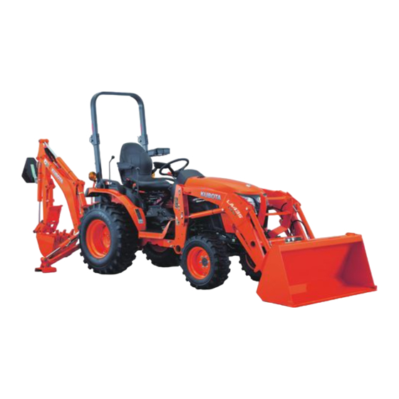
Kubota B2301/2601 TLB ROPS Cab
* Cab is shown with optional equipment *
Kubota B2301/2601 ROPS Cab
This ROPS cab is designed and built to fit the Kubota B2301, B2601 with back-hoe installed.
Designed and Built by:
Tektite Manufacturing Inc:
427 Buffalo Street
P.O. Box 639
Winkler, MB
R6W 4A8
Canada
PH: 204-331-3463
Fax: 204-331-4159
sales@tektite.ca
www.tektite.ca
One year standard product warranty provided by Tektite.
Advertisement


Need help?
Do you have a question about the B2301 TLB ROPS Cab and is the answer not in the manual?
Questions and answers