
Related Manuals for RJG Lynx MCSG-B-159-4000


Summary of Contents for RJG Lynx MCSG-B-159-4000
- Page 1 PRODUCT MANUAL PRODUCT MANUAL Lynx™ Multi‑Channel Strain Gage 4,000‑Pound Button Sensor MCSG‑B‑159‑4000 Training and Technology for Injection Molding...
- Page 2 PRINT DATE 12.02.2021 REVISION NO.
-
Page 3: Table Of Contents
PRODUCT MANUAL Lynx™ Multi‑Channel Strain Gage 4,000‑Pound Button Sensor MCSG‑B‑159‑4000 INTRODUCTION DISCLAIMER PRIVACY ALERTS ABBREVIATIONS PRODUCT DESCRIPTION APPLICATIONS BUTTON‑STYLE SENSORS SENSOR AND EJECTOR PIN SIZE SELECTION CHARTS OPERATION INDIRECT/UNDER PIN STRAIN GAGE SENSORS DIMENSIONS SENSOR CABLE LENGTHS INSTALLATION INSTALLATION OVERVIEW CLAMP PLATE (TYPICAL) INSTALLATION CLAMP PLATE (HEAD‑TO‑HEAD) INSTALLATION EJECTOR PLATE INSTALLATION... - Page 4 PRODUCT MANUAL Lynx™ Multi‑Channel Strain Gage 4,000‑Pound Button Sensor MCSG‑B‑159‑4000 INSTALLATION (CONTINUED) EJECTOR PLATE INSTALLATION SENSOR CONNECTIONS POCKET SENSOR CABLE CHANNELS SENSOR CABLE RETENTION HIGH‑TEMPERATURE (MCSG‑B‑127‑50/125/500/2000‑H) SENSOR PLATE INSTALLATION NON‑STANDARD INSTALLATIONS STATIC (NON‑MOVING) EJECTOR PINS STATIC (NON‑MOVING) EJECTOR PINS MULTIPLE EJECTOR PINS STATIC PIN EXAMPLE STATIC TRANSFER PIN EXAMPLES INSTALLATION VALIDATION...
- Page 5 4,000‑Pound Button Sensor MCSG‑B‑159‑4000 MAINTENANCE CLEANING TESTING & CALIBRATION TESTING SENSORS CALIBRATION COMMON FACTORS AFFECTING SENSOR RECALIBRATION WARRANTY RJG, INC. STANDARD THREE‑YEAR WARRANTY PRODUCT DISCLAIMER TROUBLESHOOTING INSTALLATION ERRORS EJECTOR PIN ISSUES SENSOR HEAD ISSUES CASE AND CABLE ISSUES CUSTOMER SUPPORT RELATED PRODUCTS LYNX STRAIN GAGE EIGHT‑CHANNEL SENSOR PLATE SG‑8...
- Page 6 NOTES Lynx™ Multi‑Channel Strain Gage 4,000‑Pound Button Sensor MCSG‑B‑159‑4000 | Product Manual...
-
Page 7: Introduction
This guide must be kept available for reference at all times. DISCLAIMER PRIVACY Inasmuch as RJG, Inc. has no control Designed and developed by RJG, Inc. over the use to which others may put Manual design, format and structure this material, it does not guarantee that copyright 2021 RJG, Inc. - Page 8 NOTES Lynx™ Multi‑Channel Strain Gage 4,000‑Pound Button Sensor MCSG‑B‑159‑4000 | Product Manual...
-
Page 9: Product Description
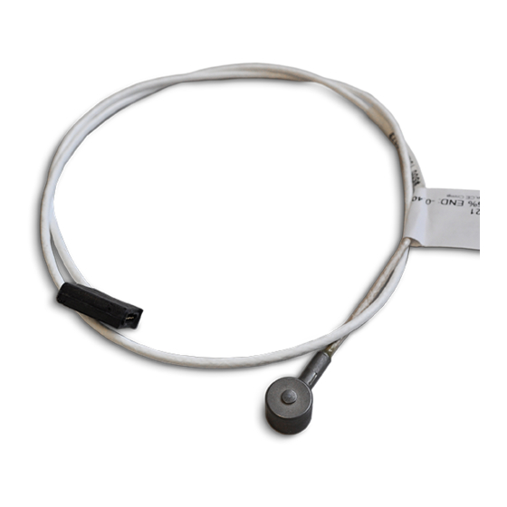
PRODUCT DESCRIPTION The MCSG‑B‑159‑4000 sensor from RJG, Inc. is a multi‑channel, digital strain gage, 0.625” (15,88 mm) button‑style cavity pressure sensor that can withstand forces of up to 4,000 lb. (17.79 kN) and temperatures of up to 250 °F (120 °C— standard sensors) or 425 °F (220 °C—... -
Page 10: Sensor And Ejector Pin Size
SELECTION CHARTS The charts below are only a guide. In order to assure correct sensor selection for your application, please contact RJG. Locate the pin size that will be used and match it to the location on the part (near the end of fill or near the gate). - Page 11 SENSOR AND EJECTOR PIN SIZE (continued) 2. Metric Units LOW PRESSURE HIGH PRESSURE Pin Size Sensor Model(s) Sensor Model(s) MCSG-B-127-125/500 MCSG-B-127-125/500 MCSG-B-127-125/500 MCSG-B-127-125/500 MCSG-B-127-125/500 MCSG-B-127-125/500 MCSG-B-127-125/500 MCSG-B-127-125/500/2000 MCSG-B-127-125/500 MCSG-B-127-500/2000 MCSG-B-127-500/2000 MCSG-B-127-500/2000, MCSG-B-159-4000 MCSG-B-127-500/2000 MCSG-B-127-500/2000, MCSG-B-159-4000 MCSG-B-127-500/2000 MCSG-B-127-500/2000, MCSG-B-159-4000 MCSG-B-127-500/2000, MCSG-B-159-4000 MCSG-B-127-500/2000, MCSG-B-159-4000 MCSG-B-127-500/2000, MCSG-B-159-4000 MCSG-B-127-500/2000, MCSG-B-159-4000...
-
Page 12: Operation
The SG/LX8‑S‑ID is connected to the placed on the pin and transferred to the RJG, Inc. eDART system, which records sensor. and displays the sensor’s measurement The voltage or measurement is carried for operator aid in process control. -
Page 13: Dimensions
DIMENSIONS SENSOR CABLE LENGTHS Cable lengths are determined at time of order. Each MCSG‑B‑159‑4000 is custom‑fit for application. SPECIFY CABLE LENGTH AT ORDER Product Manual | Lynx™ Multi‑Channel Strain Gage 4,000‑Pound Button Sensor MCSG‑B‑159‑4000... - Page 14 NOTES Lynx™ Multi‑Channel Strain Gage 4,000‑Pound Button Sensor MCSG‑B‑159‑4000 | Product Manual...
-
Page 15: Installation
INSTALLATION CLAMP PLATE INSTALLATIONS Sensors may be placed in the clamp plate behind transfer pins, or in the ejector plate Typical Head‑to‑Head behind ejector pins. Installation location—in the clamp plate or ejector plate—depends upon mold real estate and customer preference. Transfer pins protect the sensor from damaging shock loads that are applied when the ejector plate moves forward... -
Page 16: Installation Overview
INSTALLATION OVERVIEW CLAMP PLATE (TYPICAL) INSTALLATION CLAMP PLATE (TYPICAL) INSTALLATION Apply the clamp plate (typical) installation B Plate or to instances where the ejector and transfer Cavity Insert pins are less than 0.28” (7,0 mm) in diameter. The sensor connector plate is mounted Ejector Pin on the mold. -
Page 17: Ejector Plate Installation
If the angle is greater than 30°, contact RJG customer support for assistance in verifying suitability for use with an RJG sensor (refer to “Customer Support”... -
Page 18: Installation Specifications
DIMENSIONS IN INCHES [MM], UNLESS NOTED Drawn: K.J.Brettschneider TOLERANCES UNLESS SPECIFIED: XXX = 0.003 [0.08] Design: XX = 0.01 [0.3] RJG, Inc. Lynx™ Multi‑Channel Strain Gage 4,000‑Pound Button Sensor MCSG‑B‑159‑4000 | Product Manual Check: M.Groleau ANGLES = 3 30 Date: 12.02.2021... - Page 19 DETAIL C Drawn: K.J.Brettschneider TOLERANCES UNLESS SPECIFIED: XXX = 0.003 [0.08] SCALE 2.5 : 1 Design: XX = 0.01 [0.3] Check: M.Groleau ANGLES = 3 30 Date: 12.02.2021 Product Manual | Lynx™ Multi‑Channel Strain Gage 4,000‑Pound Button Sensor MCSG‑B‑159‑4000 RJG, Inc.
- Page 20 INSTALLATION SPECIFICATIONS (continued) CLAMP PLATE (TYPICAL) INSTALLATION 1. Sensor Head Pocket Sensor and transfer pin head pockets are machined into the clamp plate. The sensor pockets must be centered under the selected ejector pin measuring 0.635” +0.005/‑0.0 (16,13 mm ±0,10 [ ]) DIA, at right and 0.500”...
- Page 21 INSTALLATION SPECIFICATIONS (continued) CLAMP PLATE (TYPICAL) INSTALLATION 3. Ejector Pin Head Pocket Machine a pocket for the ejector pin head in the ejector retainer plate that is equal to the ejector pin head DIA plus 0.02” (0,5 mm [ at right]) MIN per side. Allow clearance above the ejector pin head.
-
Page 22: Clamp Plate (Head-To-Head) Installation
DIMENSIONS IN INCHES [MM], UNLESS NOTED Drawn: K.J.Brettschneider TOLERANCES UNLESS SPECIFIED: XXX = 0.003 [0.08] Design: XX = 0.01 [0.3] Check: M.Groleau RJG, Inc. Lynx™ Multi‑Channel Strain Gage 4,000‑Pound Button Sensor MCSG‑B‑159‑4000 | Product Manual ANGLES = 3 30 Date: 12.02.2021... - Page 23 Drawn: K.J.Brettschneider TOLERANCES UNLESS SPECIFIED: DETAIL H XXX = 0.003 [0.08] Design: SCALE 2 : 1 XX = 0.01 [0.3] Check: M.Groleau ANGLES = 3 30 Date: 12.02.2021 Product Manual | Lynx™ Multi‑Channel Strain Gage 4,000‑Pound Button Sensor MCSG‑B‑159‑4000 RJG, Inc.
- Page 24 INSTALLATION SPECIFICATIONS (continued) CLAMP PLATE (HEAD‑T0‑HEAD) INSTALLATION 1. Sensor Head Pocket Sensor head pockets are machined into the clamp plate. The sensor pockets must be centered under the selected ejector pin measuring 0.635” +0.005/‑0.0 (16,13 mm ±0,10 [ at right]) DIA, and 0.500” +0.002/ ‑0.001 (12,7 mm ±‑0,04 [ at right]) deep, with an added clearance of 0.01”...
- Page 25 INSTALLATION SPECIFICATIONS (continued) CLAMP PLATE (HEAD‑T0‑HEAD) INSTALLATION 3. Transfer Pin Shaft and Head Pocket Machine a pocket for the transfer pin shaft in the ejector plate with an H7/g6 fit for 0.5” (12 mm [ at right]) MIN. Machine a pocket for the transfer pin head in the ejector plate that is equal to the transfer pin head DIA plus 0.02”...
-
Page 26: Cover Plate-Clamp Plate Installations
INSTALLATION SPECIFICATIONS (continued) COVER PLATE—CLAMP PLATE INSTALLATIONS The cover plate must be made of SAE 1080 steel (AFNOR XC70/XC80), 32HRC. The cover plate may be an additional, whole plate added to the stack and secured with screws ( below, ), or an integrated plate made to embed into the clamp plate and secured with screws left below, right Lynx™... -
Page 27: Installation (Continued)
) in the cover plate on each side of at right the sensor diameter to avoid any bending of the cover; incorporate and install other screws as necessary to secure cover. RJG recommends the use of 8‑36 or 10‑32 (M4 or M5). Countersink screw heads for cover... -
Page 28: Ejector Plate Installation
DIMENSIONS IN INCHES [MM], UNLESS NOTED Drawn: K.J.Brettschneider TOLERANCES UNLESS SPECIFIED: Design: XXX = 0.003 [0.08] XX = 0.01 [0.3] Check: M.Groleau RJG, Inc. Lynx™ Multi‑Channel Strain Gage 4,000‑Pound Button Sensor MCSG‑B‑159‑4000 | Product Manual ANGLES = 3 30 Date: 12.02.2021... - Page 29 DIMENSIONS IN INCHES [MM], UNLESS NOTED 0.24–0.40 [6.0–10.0] 0.025 [0.6] Drawn: K.J.Brettschneider TOLERANCES UNLESS SPECIFIED: XXX = 0.003 [0.08] Design: XX = 0.01 [0.3] Check: M.Groleau ANGLES = 3 30 Date: 12.02.2021 Product Manual | Lynx™ Multi‑Channel Strain Gage 4,000‑Pound Button Sensor MCSG‑B‑159‑4000 RJG, Inc.
- Page 30 INSTALLATION SPECIFICATIONS (continued) EJECTOR PLATE INSTALLATION 1. Sensor Pocket Machining Sensor pockets are machined into the ejector plate. The pockets must be centered under the selected ejector pin measuring 0.635” +0.005/‑0.0 (16,13 mm +/‑0,10 [ ]) DIA, and 0.500” +0.003/‑ at right 0.0 (12,7 mm +/‑0,01 [ ]) deep.
-
Page 31: Sensor Connections Pocket
INSTALLATION SPECIFICATIONS (continued) SENSOR CONNECTIONS POCKET The sensor electronics connections are made within the plate to the SG‑8 sensor plate mounted on the outside of the plate. Dimensions shown for depths will CAUTION change if a recessed cover plate is utilized; account for recessed cover plate depth in design and machining if applicable. -
Page 32: Sensor Cable Channels
INSTALLATION SPECIFICATIONS (continued) SENSOR CABLE CHANNELS Machine a cable channel width of 0.25” (6 mm [ ]) and depth of 0.38” (9,7 mm at right ]) for a single sensor; if more than at right one sensor will be placed in the channel, provide a width of 0.50”... -
Page 33: Sensor Cable Retention
INSTALLATION SPECIFICATIONS (continued) SENSOR CABLE RETENTION Sensor cable retention strategies must be considered during the mold design phase. Cables are often not the exact size needed, or do not easily remain in the cable channels during assembly and must be retained using one or more of the following methods. Cable Pocket Cover—Washer Style Cable Clip Cable Clip... - Page 34 ( ) for the cable pocket with which to right retain extra cable. Though RJG does not currently provide a solution specifically for this application, plastic or metal discs with a centrally‑located hole, retained by a single bolt through the center, can be used to easily retain cable within the pocket.
-
Page 35: High-Temperature (Mcsg-B-127-50/125/500/2000-H) Sensor Plate Installation
The following depicts such an installation. For assistance in designing an appropriate installation to prevent heat damage to the sensor electronics, contact RJG customer support (“Customer Support” on page 52). C-SG/LX8-S-0.5/1.0/2.0 SG-8 to SG/LX8-S-ID Cable... -
Page 36: Non-Standard Installations
( ) if at right (2,5 mm ) diameter or larger. Please part thickness is less than or equal to 0.06” contact RJG Customer Support for (1,5 mm), or 0.012” (0,3 mm [ ]) if installation of static pins smaller at right the part thickness at pin location is greater than 3/32”... -
Page 37: Static (Non-Moving) Ejector Pins
5. Pin and O‑Ring Bore Installation Use an O‑ring lubricant to help prevent damage when inserting the pin into the bore. Many silicone‑based lubricants can damage silicone O‑rings. RJG, Inc. recommends P‑80 THIX lubricant from International Products Corporation (http://www.ipcol.com/shopexd. asp?id=31). Rotate the pin as it is being inserted to ease installation and limit potential O‑ring damage. - Page 38 NON‑STANDARD INSTALLATIONS (continued) 6. Sensor Readings Data from the same mold is pictured below (typical results—not guaranteed). Without O‑Ring Installation With O‑Ring Installation Above Left: Three sensors are reading too Above Right: The template and solid lines low due to contamination—without O‑rings after four months of continuous production;...
-
Page 39: Multiple Ejector Pins
NON‑STANDARD INSTALLATIONS (continued) MULTIPLE EJECTOR PINS PIN, SENSOR, & PLATE INSTALLATION Ejector pins are often grouped in small areas that do not allow for traditional cavity pressure senor installation. Read and follow all instructions, and refer to the provided figures to properly install sensors with multiple ejector pins. -
Page 40: Static Pin Example
NON‑STANDARD INSTALLATIONS (continued) STATIC PIN EXAMPLE Lynx™ Multi‑Channel Strain Gage 4,000‑Pound Button Sensor MCSG‑B‑159‑4000 | Product Manual... -
Page 41: Static Transfer Pin Examples
NON‑STANDARD INSTALLATIONS (continued) STATIC TRANSFER PIN EXAMPLES Product Manual | Lynx™ Multi‑Channel Strain Gage 4,000‑Pound Button Sensor MCSG‑B‑159‑4000... - Page 42 NOTES Lynx™ Multi‑Channel Strain Gage 4,000‑Pound Button Sensor MCSG‑B‑159‑4000 | Product Manual...
-
Page 43: Installation Validation
INSTALLATION VALIDATION SENSOR INSTALLATION CHECK—CLAMP PLATE (TYPICAL) INSTALLATIONS Verify that the each sensor, transfer pin, and ejector pin pocket is machined correctly. PRE‑ASSEMBLY CHECKS 1. Indentation Test (with sensor) With the clamp plate disassembled, sensor in place, and cover plate removed, push the sensor and transfer pin forward;... - Page 44 SENSOR INSTALLATION CHECK—CLAMP PLATE (TYPICAL) INSTALLATION (continued) 3. Indentation Test (with Ejector Pin) With the ejector pin installed, push on the ejector pin; verify the clearance of 0.012” (0,3 mm (or 1/5 part thickness)) exists between the bottom of the ejector pin head and the ejector retainer plate surface.
-
Page 45: Post-Assembly Checks
SENSOR INSTALLATION CHECK—CLAMP PLATE (TYPICAL) INSTALLATION (continued) POST‑ASSEMBLY CHECKS 1. Protrusion Test (without sensor) With the ejector and transfer pins installed, the ejector plate in injection position, and the ejector plate fixed towards clamp plate, press the ejector and transfer pin together, towards the cavity;... - Page 46 SENSOR INSTALLATION CHECK—CLAMP PLATE (TYPICAL) INSTALLATION (continued) 2. Indentation Test (without sensor) With the ejector and transfer pins installed, the ejector plate in the injection position, and the ejector plate fixed towards clamp plate, press the ejector and transfer pin together, away from the cavity;...
-
Page 47: Sensor Installation Check-Clamp Plate (Head-To-Head) Installations
SENSOR INSTALLATION CHECK—CLAMP PLATE (HEAD‑TO‑HEAD) INSTALLATIONS Verify that the each sensor, transfer pin, and ejector pin pocket is machined correctly. PRE‑ASSEMBLY CHECKS 1. Indentation Test (without sensor) With only the transfer pin installed, push on the transfer pin head and verify a clearance of exists 0.012”... - Page 48 SENSOR INSTALLATION CHECK—CLAMP PLATE (HEAD‑TO‑HEAD) INSTALLATION (continued) 3. Indentation Test (with sensor) With the clamp plate disassembled, sensor in place, and cover plate removed, push the sensor and transfer pin forward; there should be 0.012–0.02” (0,3–0,5 mm) clearance between the sensor bottom and the clamp plate/sensor pocket bottom before the cover plate surface.
-
Page 49: Post-Assembly Checks
SENSOR INSTALLATION CHECK—CLAMP PLATE (HEAD‑TO‑HEAD) INSTALLATION (continued) POST‑ASSEMBLY CHECKS Verify that the each sensor, transfer pin, and ejector pin pocket is machined correctly. 1. Protrusion Test (without sensor) With the ejector and transfer pins installed, the ejector plate in injection position, and the ejector plate fixed towards clamp plate, press the ejector and transfer pin together, towards the cavity;... - Page 50 SENSOR INSTALLATION CHECK—CLAMP PLATE (HEAD‑TO‑HEAD) INSTALLATION (continued) 2. Indentation Test (without sensor) With the ejector and transfer pins installed, the ejector plate in the injection position, and the ejector plate fixed towards clamp plate, press the ejector and transfer pin together, away from the cavity;...
-
Page 51: Sensor Installation Check-Ejector Plate Installations
SENSOR INSTALLATION CHECK—EJECTOR PLATE INSTALLATIONS Verify that the each sensor, transfer pin, and ejector pin pocket is machined correctly. PRE‑ASSEMBLY CHECKS 1. Indentation Test (with Ejector Pin) With the ejector pin installed, push on the ejector pin; verify the clearance of 0.012” (0,3 mm (or 1/5 part thickness)) exists between the bottom of the ejector pin head and the ejector plate surface. -
Page 52: Sensor Installation Check-Static Pin Installations
SENSOR INSTALLATION CHECK—STATIC PIN INSTALLATIONS Verify that the each sensor and static pin pocket is machined correctly. 2. Protrusion Test (without sensor) With only the static pin installed, push on the static pin; verify the pin protrudes clearance above the pin head equal to 1/5th of the part thickness at pin location if part thickness is less than or equal to 0.06”... -
Page 53: Cleaning
MAINTENANCE Strain gage sensors require little RJG, Inc. offers the following tools to test maintenance. sensors. CLEANING 4. Sensor eValuator Pull sensors from the mold and clean out The Sensor eValuator provides diagnostics the pockets and channels when a mold on typical sensor problems such as sensor is pulled for preventative maintenance. -
Page 54: Calibration
(less than 40% of full scale) of 2% is more than sufficient, and is used show less calibration shift than sensors that by RJG as the specification for repaired run at the high end of their range. sensors. -
Page 55: Warranty
RJG, INC. STANDARD THREE‑YEAR 5. Sensor Operating Temperature WARRANTY The higher the mold temperature, the RJG, Inc. is confident in the quality and greater the potential for calibration shift. robustness of the MCSG‑B‑159‑4000 Below 212 °F (100 °C), calibration usually cavity pressure sensors, and so are remains stable. - Page 56 NOTES Lynx™ Multi‑Channel Strain Gage 4,000‑Pound Button Sensor MCSG‑B‑159‑4000 | Product Manual...
-
Page 57: Troubleshooting
TROUBLESHOOTING INSTALLATION ERRORS EJECTOR PIN ISSUES 1. Pin size, expected pressure,and/or expected temperature not appropriate for selected sensor. • Refer to “Sensor and Ejector Pin Size” on page 2. 2. Ejector pin is located behind mold surface with angle greater than 30° at right). -
Page 58: Sensor Head Issues
INSTALLATION ERRORS (continued) SENSOR HEAD ISSUES 4. Ejector Pin head diameter is larger than sensor pocket diameter ( at right). • Counterbore the ejector plate, or chamfer the pin head to ensure that the pin rests only on the sensor nub. 5. -
Page 59: Case And Cable Issues
9. Sensor case is mounted on surface that exceeds temperature rating. • Do not mount the Lynx case on surface that exceeds the recommended temperature rating. Contact RJG, Inc. Customer support for high‑temperature applications. Product Manual | Lynx™ Multi‑Channel Strain Gage 4,000‑Pound Button Sensor MCSG‑B‑159‑4000... -
Page 60: Customer Support
CUSTOMER SUPPORT Contact RJG’s Customer Support team by phone or email. RJG, Inc. Customer Support P: 800.472.0566 (Toll Free) P: +1.231.933.8170 email: globalcustomersupport@rjginc.com www.rjginc.com/support Lynx™ Multi‑Channel Strain Gage 4,000‑Pound Button Sensor MCSG‑B‑159‑4000 | Product Manual... -
Page 61: Related Products
RELATED PRODUCTS The MCSG‑B‑159‑4000 are designed to be used with the following RJG, Inc. products as a system for use with the eDART process control and monitoring system. LYNX STRAIN GAGE EIGHT‑CHANNEL SENSOR PLATE SG‑8 The Lynx strain gage eight‑channel sensor plate SG‑8 (... -
Page 62: Similar Products
SIMILAR PRODUCTS RJG, Inc. offers a wide array of cavity pressure sensors for each application— strain gage, single‑channel, multi‑channel, and digital. LYNX MULTI‑CHANNEL STRAIN GAGE SENSORS The Lynx multi‑channel strain gage sensors MCSG‑B‑127‑125/500/2000 ( at right) provide the same strain gage technology and indirect installation as the MCSG‑B‑159‑4000 sensors, but with a... - Page 64 P +39 335 178 4035 P +01 231 947‑3111 sales@it.rjginc.com F +01 231 947‑6403 it.rjginc.com sales@rjginc.com www.rjginc.com MEXICO RJG MEXICO SINGAPORE RJG (S.E.A.) PTE LTD Chihuahua, Mexico Singapore, Republic of P +52 614 4242281 Singapore sales@es.rjginc.com P +65 6846 1518 es.rjginc.com sales@swg.rjginc.com en.rjginc.com...
Need help?
Do you have a question about the Lynx MCSG-B-159-4000 and is the answer not in the manual?
Questions and answers