
Related Manuals for Wintriss ShopFloorConnect SMI 2

Summary of Contents for Wintriss ShopFloorConnect SMI 2
- Page 1 Wintriss Controls Group Addendum – SMI 2 – User Guide ShopFloorConnect Machine Interface 1146200 – Rev. C October 27, 2021 SFC Support Hotline 800-586-8324 (Option 3) 8-5 EST...
-
Page 2: Table Of Contents
Contents Specifications ..............................3 Main Menu ..............................4 Main Menu Icon/Button Selections ......................5 Dashboard ..............................6 Downtime..............................7 Job Manager ..............................8 Load Next Job ..............................9 Preset ................................10 Batch Segment Preset ..........................11 Admin Menu ............................... 12 Security Settings ............................ - Page 3 The one exception to the 30-character limit is the Primary when it is set to ‘Tool # (123)’. This particular primary type is intended to match the Wintriss SmartPAC 1 and SmartPAC 2 controls and is limited to 7 numeric characters only.
-
Page 4: Specifications
Specifications Installation Category Enclosure: 8.00 x 10.08 x 4.00 in. (101.6 x 203.2 x 256.0 mm) NEMA 12, IP 66 Dimensions Panel mount: 9.2 x 7.7 x 4.25 in. (234 x 196 x 108 mm) Electrical Input: 100-240 Vac, 40 W, 50-60 Hz (System Power) 24 Vdc +/- 15%, 30 W When installed, this equipment shall have, in close proximity and easily... -
Page 5: Main Menu
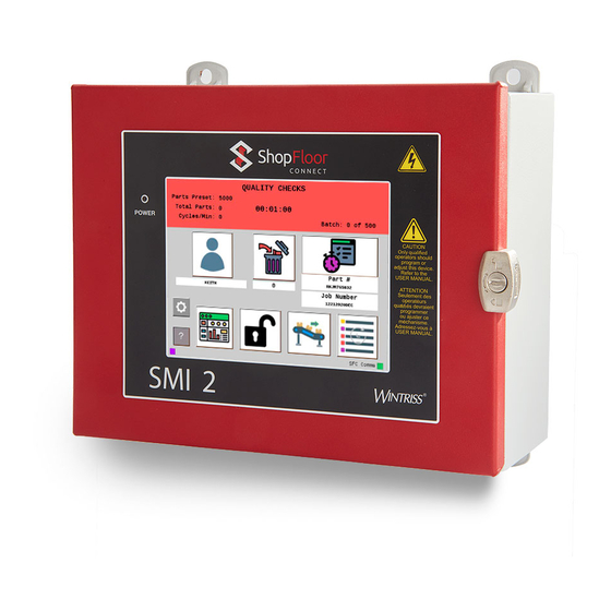
Main Menu Figure 1 - SMI 2 Main Menu The Status Banner at the top of the main menu is color-coded for the five different SFC states: Green (Running), Blue (Idle), Red (Unplanned), Yellow (Changeover), Purple (Planned). It also shows the current status and duration as well as the current count info and production rate. -
Page 6: Main Menu Icon/Button Selections
Main Menu Icon/Button Selections Select the ‘Operator’ icon to enter the operator number or name (Optional Scan Field). Select the ‘Rejects’ (scrap) icon to manually enter the desired quantity of defective parts. Select the ‘Job Manager’ icon to enter job related information, start a new job or to end the current job. -
Page 7: Dashboard
Dashboard Figure 2 - Dashboard Menu The DASHBOARD menu shows MTBF (Mean Time Between Failures) and the Analog values from any connected analog sensor (e.g. Temperature, Current, Pressure, etc.). Mean time between failures (MTBF) refers to the average amount time between Unplanned Downtime occurrences. -
Page 8: Downtime
Downtime Figure 3- The Downtime Menu Use this menu to choose the appropriate downtime reason. Use the ‘Previous’ or ‘Next’ buttons to display the previous or next set of reasons. Press the ‘Cancel’ button to skip setting the downtime reason and return to the Main Menu. Press the reason to select it as the current downtime reason. Note: Downtime reasons can be 30 characters or less. -
Page 9: Job Manager
Job Manager Figure 4 - The Job Manager Menu Use this menu to Scan/Enter Job information - Primary (e.g. Tool, Part, Mold, Fixture, SKU, Material, Item, etc.) is required. Optionally Scan/Enter Job Number, Preset (qty. parts to be produced), and Batch. The BATCH allows the operator to set the quantity of parts to make for this batch. -
Page 10: Load Next Job
Load Next Job Figure 5 - Load Next Job The ‘Load Next Job’ menu launches when the Next button on the Job manager is selected, and Scheduler is enabled. Job information from the ShopFloorConnect Scheduler is displayed and gets consumed by selecting ‘Load’. 1146200 Addendum October 2021... -
Page 11: Preset
Preset Figure 6 - Setting the Preset (set up for a scanner) Selecting the scan/edit to the right of ‘Preset’ allows the operator to enter the total quantity of parts to be made. Figure 6 above shows the field set up for scanning. When the quantity is reached, the SMI’s inhibit relay will open and stop the machine if ‘Stop on Preset’... -
Page 12: Batch Segment Preset
Batch Segment Preset Figure 7 - Batch Segment Preset Value The ‘Batch Segment’ menu allows the operator to enter a batch quantity. Often, it’s programmed to stop the machine when a certain quantity of parts is reached so a basket can be switched out or to QC a part after X number of cycles. -
Page 13: Admin Menu
Admin Menu Figure 8- Admin Menu Icon/Button Selections Select ‘Security Settings’ to set or change Admin and Adjust Scrap passwords. Also, to reset all settings to their Factory Defaults. Select ‘Settings’ to set various systems parameters like Screen and Scanner defaults, Network settings, State Hold and SFC Parameter Downloads. -
Page 14: Security Settings
Security Settings Figure 9 - Security Settings When the ‘Password Required to Access Admin’ is set to ‘Enabled’, the user will be required to enter a password to access the admin Menus. When the ‘Password Required to Adjust Rejects’ is set to ‘Enabled’, the user will need a password to change the reject count. -
Page 15: Confirm Reset To Factory Defaults
Confirm Reset to Factory Defaults Figure 10 – Confirm Reset to Factory Defaults Warning: Pressing the Confirm button will erase all settings you have made and return the SMI 2 to its original factory settings. Note: This includes all Downtime Reasons saved to the SMI 2. These will need to be resent from ShopFloorConnect. -
Page 16: About Smi
About SMI Figure 11 - About SMI Lists code versions, password code and SFC Support contact information. 1146200 Addendum October 2021 SMI 2 User Guide Rev. C Page 15... -
Page 17: Multipliers
Multipliers Figure 12 - Multipliers Menu The Operations/Cycle should be used when one or more cycles of the machine are required to produce a completed part. The Cycle Count Multiplier value is the number of parts created after a single cycle. The Rejects Count Multiplier value is the number of Scrap/Rejects that will be tallied and deducted from the Good Parts Count when the Scrap/Rejects input is actuated. -
Page 18: Utilities
Utilities Figure 13 - Utilities with Tools and Debug Sub-menus The ‘Force Code Download’ button forces the SMI to reboot and prompt the user to perform a Code Download. The ‘Reboot System’ button restarts the SMI 2. The ‘Calibrate Screen’ button is for calibrating the touch screen. The ‘Start Remote Access’... -
Page 19: Additional Settings - Icon/Button Selections
Additional Settings - Icon/Button Selections Select ‘Screen Defaults’ to change the language of the SMI, hide the changeover and/or Dashboard button. Select ‘Forced Dialog Settings’ to Enabled/Disable when the operator is forced to select a downtime reason before restarting the machine. Select ‘Scanner defaults’... -
Page 20: Screen Defaults
Screen Defaults Figure 14 - Screen Default Settings and Simple View When Enabled Languages that SFC currently supports are English, Spanish, Italian, and German. Check ‘Hide Changeover Button’ to hide the canned changeover dialog reason in the dialog menu. Check ‘Hide Dashboard Button’ to hide the dashboard button on the Main menu. Check ‘Hide Scrap Button’... -
Page 21: Forced Dialog Settings
Forced Dialog Settings Figure 15 - Forced Dialog Settings When enabled, the ‘Forced Dialog’ mode forces the operator to select a downtime reason before restarting the machine. The ‘Auto Back Fill’ mode automatically replaces the idle time with any selected downtime event. The ‘Manual Backfill’... -
Page 22: Scanner Defaults
Scanner Defaults Figure 16 - Scanner Default Settings Check any of the boxes for items you want the operator to be able to scan data into a field. 1146200 Addendum October 2021 SMI 2 User Guide Rev. C Page 21... -
Page 23: Production Settings
Production Settings Figure 17 - Production Settings The ‘Calculation Interval’ sets the frequency at which the SMI calculates the speed (Production Rate) of the machine. Set this to the time it takes to make 10 cycles, or 15 seconds, whichever is greater. The ‘Idle Timer’... -
Page 24: Input Settings
Input Settings Figure 18 - Input Settings The ‘Input Setup’ provides access to settings associated with the Cycle Input, Run/Idle inputs, Rate Calculation, and Analog Inputs. The ‘Enable Inputs’ shows the current on/off state of the SMI’s inputs. The ‘Enable Inputs’ gives access to the setting the way the SMI interprets state changes using the Cycle and Run/Idle inputs. -
Page 25: Input Setup
Input Setup Figure 19 - Input Setup The ‘Cycle Input’, ‘Run/Idle Input’, and ‘Analog Inputs’ allows access to the settings associated with those inputs. The ‘Rate Calculation’ provides access to the ‘Pulses Per Units’ setting which specifies the number of actuations of the cycle input that represents one increment of the speed units. -
Page 26: Cycle Input Setup
Cycle Input Setup Figure 20 - Cycle Input Setup The ‘Cycle Input’ allows the operator to modify the cycle input signal to match the requirements of the SMI. The choices are ‘No additional Timing’ and ‘Off Delay’. The ‘No additional Timing’ selection makes no modifications to the input signal. The ‘Off Delay’... -
Page 27: Run/Idle Input Setup
Run/Idle Input Setup Figure 21 - Run/Idle Input Setup Menu The ‘Run/Idle Input’ allows the operator to modify the run/idle input signal to match the requirements of the SMI. The choices are ‘No additional Timing’ and ‘Off Delay’. The ‘No Additional timing’ selection makes no modifications to the input signal. The ‘Off delay’... -
Page 28: Rate Calculation
Rate Calculation Figure 22 - Rate Calculation Setting The ‘Pulses per Unit’ specifies the number of actuations of the cycle input that represents one increment of the speed units. This is typically set to 1. 1146200 Addendum October 2021 SMI 2 User Guide Rev. -
Page 29: Analog Setup Menu
Analog Setup Menu Figure 23- Analog Input Setup Menu Select the ‘Channel 1 Alias Selection’ to change to the right metric (Temperature (F), Temperature (C), Pressure, or Volts). Do the same for ‘Channel 1 Alias Selection’. Select the Max to set your channel max to (Range is 10-4095). The max number is mapped to a percentage (0-100%) based on the 10-volt input the analog will receive. -
Page 30: Enable Inputs
Enable Inputs Figure 24- The Enable Inputs The ‘Run/Idle Sense Input’ is an optional signal the SMI can use to determine if the machine is running. If this signal is not supplied, the SMI uses the Cycle Input and Production Idle Timer to determine the Run/Idle state. - Page 31 Hold State Settings Figure 25 - Hold State Settings Release Hold State – There are 3 options. One, release hold state manually by selecting the hold state button. Two, release hold state when X number of cycles are produced. Three, release hold state after X number of seconds.
-
Page 32: Production Parameter Download
Production Parameter Download Figure 26- Production Parameter Download Menu Check ‘Get Count Factors’ to download the Operations Per Cycle and Parts Per Cycle count modifier settings at the start of a new job. Check ‘Get Production Idle timer’ to download the Production Idle timer setting at the start of a new job. -
Page 33: Smi 2 Job Manager Settings
SMI 2 Job Manager Settings Figure 27 - Job Manager Settings This Menu allows you to select names (aliases) for your Primary Item and Job Number. Select ‘Primary Name Selection’ to scroll through the selections. Choices for ‘Primary Name Selection’ are Tool # (123), Tool # (abc123), Part #, Mold #, Fixture #, SKU #, Material #, and Item Number. -
Page 34: Forced Operator Login
Forced Operator Login Figure 28 – Forced Operator Login Settings When Forced Operator Login is enabled a full screen message is displayed indicating that the operator must login and the operator fields are erased from the SMI2. In addition, the SMI2 inhibit circuit will be opened until an operator is logged in. -
Page 35: Network Settings
Network Settings Figure 29- Network Settings Select the Network IP Settings button to input Static IP address settings. Select the Wireless Settings button to configure wireless settings, SSID, Passcode etc. Note: For your SMI 2 to connect to your network wirelessly, the Optional Wireless Kit (802.11 B/N/B) must be Factory installed at time of initial order. -
Page 36: Network Ip Settings
Network IP Settings Figure 30 – Network IP Settings This menu enables the user to set the network parameters for a static IP address or allow the DHCP server to provide the address. 1146200 Addendum October 2021 SMI 2 User Guide Rev. -
Page 37: Wireless Settings
Wireless Settings Figure 31 – Wireless Settings To set the SMI-2 up to use a wireless access point, you must provide the following information: SSID, and Pass Key (Password Key). 1146200 Addendum October 2021 SMI 2 User Guide Rev. C Page 36...
Need help?
Do you have a question about the ShopFloorConnect SMI 2 and is the answer not in the manual?
Questions and answers