Table of Contents
Advertisement
FENWAL
Protection Systems
KIDDE – FENWAL, Inc.
400 Main Street
Ashland, MA 01721 USA
EX 200™
SINGLE ZONE CONTROL PANEL
Installation, Operation and Maintenance Manual
Publication FSS/MC-519 Rev. BC
Issued April 2009
Telephone: 508-881-2000
Facsimile: 508-485-3115
After-hours emergency telephone: 508-624-7200
Web:
www.fenwalprotection.com
Advertisement
Table of Contents

Related Manuals for Fenwal EX 200

Summary of Contents for Fenwal EX 200
- Page 1 FENWAL Protection Systems KIDDE – FENWAL, Inc. 400 Main Street Ashland, MA 01721 USA EX 200™ SINGLE ZONE CONTROL PANEL Installation, Operation and Maintenance Manual Publication FSS/MC-519 Rev. BC Issued April 2009 Telephone: 508-881-2000 Facsimile: 508-485-3115 After-hours emergency telephone: 508-624-7200 Web: www.fenwalprotection.com...
- Page 2 THIS MANUAL IS PROVIDED AS AN INSTALLATION, OPERATION AND MAINTENANCE GUIDE FOR THE EX 200™ SINGLE ZONE CONTROL PANEL. THE CONTROL PANEL SHOULD NOT BE INSTALLED IN ANY SYSTEM UNLESS THE SPECIFIC APPLICATION AND SYSTEM DESIGN HAS BEEN REVIEWED AND APPROVED BY FENWAL.
-
Page 3: Table Of Contents
SAFETY WARNING PRIORITIZATION ................5 INCOMING INSPECTION ....................5 INTRODUCTION.......................6 Description........................6 Features and Benefits....................7 Front Panel Indicators....................9 EX 200™ System Controls ..................12 Terminal Definitions .....................13 EX 200™ Internal Trouble Indicators................16 MECHANICAL INSTALLATION ..................18 ELECTRICAL INSTALLATION ..................20 System Wiring Requirements ..................20 AC Power Connection ....................21 Battery Installation .......................22... - Page 4 FIGURES Figure 1: Exterior View of EX 200™ with Front Door Open ..........8 Figure 2: Location of Components on Printed Circuit Board........... 11 Figure 3: Detailed View of Trouble Indicators ..............16 Figure 4: Standard Panel Outline Drawing ..............18 Figure 5: Larger Enclosure Panel Outline Drawing............
-
Page 5: Important Information
FENWAL explosion protection system distributor or the IEP Design Engineering or Service Department at KIDDE-FENWAL for assistance and instructions. Not all explosions can be suppressed or isolated and FENWAL cannot and does not guarantee that its equipment will suppress or isolate explosions that might occur at your facility, or in your equipment. - Page 6 WARNING THE WARNINGS, INSTRUCTIONS, SAFETY NOTES AND OTHER NOTES IN THIS MANUAL, AND ALL OTHER INFORMATION PROVIDED, MUST BE FOLLOWED EXACTLY. THIS EQUIPMENT CONTROLS FENWAL, INCOM, KIDDE FIRE PROTECTION, AND KIDDE DEUGRA HIGH RATE DISCHARGE (HRD) EXTINGUISHERS CONTAINING EXPLOSION SUPPRESSION AGENT UNDER HIGH PRESSURE AND FENWAL HIGH SPEED EXPLOSION ISOLATION VALVES, SOME OF WHICH USE ELECTRO-EXPLOSIVE DEVICES.
-
Page 7: Safety Warning Prioritization
INCOMING INSPECTION Upon receiving the EX 200™ Single Zone Control Panel, inspect the shipping carton for damage before unpacking it. Notify the delivering carrier and FENWAL immediately if the carton or equipment appears damaged. Unpack the carton and examine the contents for damage. -
Page 8: Introduction
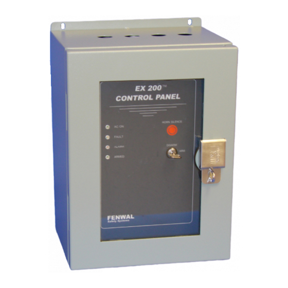
The EX 200™ is packaged in a NEMA 4X Stainless Steel, or a NEMA 4 (IP 55) powder- coated steel, wall-mounted, enclosure as shown in Figure 1. The gray powder coating is a heat fused modified polyester that is electrostatically applied on a phospatized base. -
Page 9: Features And Benefits
Features and Benefits The EX 200™ control panel introduces new features never seen before in previous FENWAL explosion protection system controllers. After years of market research, FENWAL designed the EX 200™ to accommodate requests made by maintenance personnel, installers, service engineers, and operators. The EX 200™ offers the following new features: ... -
Page 10: Figure 1: Exterior View Of Ex 200™ With Front Door Open
HORN SILENCE PUSHBUTTON MOUNTING HOLES SYSTEM STATUS INDICATORS ARM/DISARM FRONT PANEL KEYSWITCH KNOB PROVISION FOR PADLOCK Figure 1: Exterior View of EX 200™ FENWAL Page 8 FSS/MC-519 Rev BC Protection Systems... -
Page 11: Front Panel Indicators
Fully Charged Not Satisfactorily Charged Extinguisher Low Pressure Application Dependent Application Dependent * Five second turn-on delay Up to three minute turn-on delay Table 1: FAULT Indicator Operation – External Faults FENWAL Protection Systems FSS/MC-519 Rev BC Page 9... - Page 12 The front panel key switch and remote ARM/DISARM input (if used) are connected in series. The key must be in the ARM position and the remote ARM/DISARM input closed for the EX 200™ to begin arming. Upon applying power to the control panel, the microprocessor will conduct Built-In Tests (BIT).
-
Page 13: Figure 2: Location Of Components On Printed Circuit Board
INTERFACE CONNECTION TERMINALS RESET PUSHBUTTON BATTERY CONNECTION TERMINALS BATTERY REVERSED LED S3 SWITCHES, SEE FIG. 7 AUDIBLE ALARM STICK-ON TEMPERATURE SENSOR BATTERY Figure 2: Location of Components on Printed Circuit Board FENWAL Protection Systems FSS/MC-519 Rev BC Page 11... -
Page 14: Ex 200™ System Controls
This is a two-position keyed tubular switch-lock located on the front panel. It can be connected in series with a remote ARM/DISARM switch connected to terminals 38 and 39. Both must be in the ARM/closed position for the EX 200™ to arm after a 15-second delay. -
Page 15: Terminal Definitions
5 are closed and terminals 5 and 6 are open. This relay is normally used to activate an alarm and/or to operate secondary protection systems. The relay will not de-energize until the EX 200™ is disarmed and the RESET pushbutton is pushed. Contact rating: 5A @ 30 Vdc, 5A @ 240 Vac, resistive loads only. - Page 16 FAB3 Connections, Terminals 30-32 (TB14) Terminals 30 and 31 provide continuous power to FAB3 field connection boxes used in conjunction with FENWAL’s MEX3 dynamic pressure detector. Power is not interrupted to FAB3 field connection boxes when the reset button is pressed, as power interruption would erase the history buffer contained in the FAB3.
- Page 17 Wires are connected to these terminals in the factory. The red wire is to be connected to the ‘+’ battery terminal and the black wire to the ‘-‘ battery terminal. Refer to the Battery Installation section of this manual for more information. FENWAL Protection Systems...
-
Page 18: Ex 200™ Internal Trouble Indicators
EX 200™ Internal Trouble Indicators The EX 200™ fully supervises all of the components of the system, including itself, by performing 22 tests every second. When a fault is detected, the control panel turns on the FAULT indicator and the corresponding trouble indicator inside the panel, de-energizes the appropriate trouble or warning relay depending on the fault, and sounds the horn intermittently if the system is armed. -
Page 19: Table 2: Trouble Indicators Definitions
Detector 1 Alarm test Detector 2 Alarm test Front Panel EED Current EED Capacitor 24 V Power Supply Battery Charger 0 V Reading Error by A/D converter Table 3: PCB Trouble Code Definitions FENWAL Protection Systems FSS/MC-519 Rev BC Page 17... -
Page 20: Mechanical Installation
¼ turn. The EX 200™ Control Panel is designed to be wall-mounted on a flat surface. Figures 4 & 5 illustrate the slots provided for mounting the control panels. Use of all slots is recommended. -
Page 21: Figure 5: Larger Enclosure Panel Outline Drawing
Figure 5: Larger Enclosure Panel Outline Drawing FENWAL Protection Systems FSS/MC-519 Rev BC Page 19... -
Page 22: Electrical Installation
Conduit must be sealed after inspection and approval of the system by a FENWAL field engineer. Conduit entry holes are atop the control panel enclosure. Holes that are not used should be plugged with NEMA rated plugs (supplied with the control panel). -
Page 23: Ac Power Connection
Figure 6: Recommended Field Wiring Termination AC Power Connection AC power is connected to the EX 200™ control panel using terminals 1, 2, and 3 located just right of the transformer as shown in Figures 2. Prior to applying power, be certain that the proper connector plug (J1) has been inserted into the PCB so that it matches the supply voltage. -
Page 24: Battery Installation
Battery Installation The EX 200™ Control Panel is provided with a 12V, 12 A-h or a 12V, 35 A-h lead acid battery. An optional 12V, 21 A-h battery is also available if required. To install the battery: 1. Unlatch and open the enclosure door using a flat screwdriver. -
Page 25: Programming
Two voltage selector plugs are provided in the accessory kit included with the EX 200™, one is label 115VAC and the other is label 230VAC. Insert the appropriate plug to match the AC power connected to the control panel. -
Page 26: Switch Bank S3
Regardless of the position of this switch, the reset button must be pressed to reset the control panel after an alarm condition. FENWAL Page 24 FSS/MC-519 Rev BC... -
Page 27: Figure 9: Det3 Vent Monitoring Wiring Schematic
The FAULT indicator remains on and the trouble relay remains de-energized, even if the trouble is cleared, until the control panel is manually reset. FENWAL Protection Systems FSS/MC-519 Rev BC... - Page 28 It is important to note that the panel cannot be armed if AC power is not present regardless of the position of Switch S3-8. FENWAL Page 26 FSS/MC-519 Rev BC...
-
Page 29: Table 4: Ex 200™ Programming Options Summary
Enables audible horn and battery backup when the panel Left Switch S3-8 is disarmed. (BATDISDL) Disconnects audible horn and battery backup when panel Right is disarmed. Table 4: EX 200™ Programming Options Summary FENWAL Protection Systems FSS/MC-519 Rev BC Page 27... -
Page 30: Operation
The green ARMED indicator will begin to blink to indicate the start of the arming process. The yellow FAULT indicator will remain illuminated during the arming process. If the system passes all external tests (15 second duration), the system will arm. FENWAL Page 28 FSS/MC-519 Rev BC Protection Systems... -
Page 31: Disarming The System
3. If DC power does not disconnect, disconnect the battery leads from the battery. 4. Close and secure the front panel and then the front door. 5. Perform lockout procedures to prevent unauthorized access. FENWAL Protection Systems FSS/MC-519 Rev BC... -
Page 32: Commissioning
COMMISSIONING After the EX 200™ and the other components of the system have been installed, wired and programmed, FENWAL-certified personnel must thoroughly check the system for proper operation before it is put into service. WARNING DO NOT CONNECT THE FIREWOLF™ OR ELECTRO-EXPLOSIVE ACTUATORS IN THE HRD EXTINGUISHERS AND EXPLOSION ISOLATION VALVES UNTIL THE SYSTEM HAS BEEN COMMISSIONED. -
Page 33: Ex 200™ Technical Specifications
Supervised circuit detects and indicates trouble conditions on systems that utilize motor operated Firewolf™ HRD extinguishers. Remote Arm/Disarm Two-terminal loop permits EX 200™ to be armed and disarmed remotely. Remote Interlock Two-terminal loop permits safe entrance into protected areas. Upon entry into a protected vessel, interlock switch on access door breaks the HRD extinguisher actuator circuit. -
Page 34: Outputs
EED Output One, 500 mJ output, minimum, capable of firing up to twelve EED actuators. Compatible with: FENWAL actuators, P/N 32-099932-007, -008, -010, -011, -101 Kidde Fire Protection 6* detonators, FSS P/N 43-044844-147 Kidde Fire Protection Metron actuators Response time after detection: less than 3.0 ms Actuation circuit disabled during power-up. -
Page 35: Ordering Information
P/N 32-091600-001 EX 200™ Accessory Kit P/N 06-129400-001 The accessory kit is included with the EX 200™ and is located inside the enclosure. The kit contains the following parts: (1) 115 Vac mains voltage selector plug. (1) 230 Vac mains voltage selector plug. -
Page 36: Products Returned To Fenwal
PRODUCTS RETURNED TO FENWAL When products are returned for test, corrective action, credit, or repair, please identify them with a FENWAL Return Material Number clearly marked on the return package and a memorandum describing the reason for return, reshipping instructions and, should a problem exist, provide us with complete information covering the problem. - Page 37 THIS PAGE IS INTENTIONALLY LEFT BLANK.
- Page 38 400 Main Street or should particular problems arise which are not covered sufficiently for the purchaser’s purpose, the Ashland, Massachusetts 01721 USA matter should be referred to KIDDE – FENWAL, Inc., Tel: (508) 881-2000 Fax: (508) 485-3115 Ashland, Massachusetts. Web: www.fenwalprotection.com...
Need help?
Do you have a question about the EX 200 and is the answer not in the manual?
Questions and answers