Advertisement
Available languages
Available languages
Quick Links
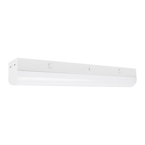
LED STRIP LIGHTS
Models: 65/700, 65/701, 65/702, 65/703, 65/706, 65/707, 65/708
INSTALLATION AND SAFETY INSTRUCTIONS
IMPORTANT: Read before installing fixture. Retain for future reference.
WARNING:
Risk of Fire or Electric Shock
• To reduce the risk of fire, electrical shock or injury to persons; read
and follow all warnings and installation instructions before installing.
• All installation should be performed by a qualified electrician.
• To avoid electric shock, ensure power is turned off before installation.
• All wiring must be installed in accordance with all Electrical Codes.
• To prevent product malfunction and/or electrical shock, this product
must be properly grounded.
• Suitable for damp locations.
• Suitable for non-insulated surface and frame. DO NOT cover fixture
with insulation liner or similar material.
• DO NOT install fixture on unstable or easily breakable surface.
• DO NOT exert force on the surface of the fixture.
Item #
Description
65/700
2' LINEAR STRIP WHITE FINISH 100-277V
65/701
4' LINEAR STRIP WHITE FINISH 100-277V
65/702
8' LINEAR STRIP WHITE FINISH 100-277V
65/703
8' LINEAR STRIP WHITE FINISH 120-347V
65/706
2' & 4' SUSPENSION KIT
65/707
8' SUSPENSION KIT
65/708
ADD ON EM
CCT INSTRUCTIONS
STEP 1: Press the Spring buttons and remove fixture cover.
INSTALLATION – Surface Mount
STEP 1: Install appropriate anchors into the ceiling or wall.
4' LF = 36 1/4"
8' LF = 83 3/8"
STEP 3: Secure fixture backplate on to the wall or ceiling
using appropriate hardware.
© Copyright 2021 Satco Products, Inc. 6/21
Finish/Details
WHITE
59" SUSPENSION LENGTH
59" SUSPENSION LENGTH
8W/1440LM/90 Min. Run Time
STEP 2: Position desired CCT to 3500K, 4000K or 5000K
as needed. After selecting CCT, secure cover.
STEP 2: Turn OFF the power and connect wires by using
wire nuts. See wiring diagram below.
STEP 4: Press the cover upward and lock it with fixture
springs. Installation of fixture is compete.
1
65/700 2' (0.610m) W
65/701 4' (1.2m) W
65/702 8' (2.4m) W
65/703 8' (2.4m) W
Volts
Temperature
100~277V
-20°C to 60°C
120~347V
–
–
–
–
–
–
Wiring Diagram
LINE
BLACK
NEUTRAL
WHITE
GROUND
GREEN
CCT
Watts
20W
3500K
30W
4000K
40W
5000K
50W
82W
–
–
–
–
–
–
Fixture
PURPLE
DIM +
GREY
DIM –
Satco Products, Inc.
Brentwood, NY 11717
Advertisement

Related Manuals for Satco NUVO 65/700


Summary of Contents for Satco NUVO 65/700
- Page 1 STEP 3: Secure fixture backplate on to the wall or ceiling STEP 4: Press the cover upward and lock it with fixture using appropriate hardware. springs. Installation of fixture is compete. Satco Products, Inc. © Copyright 2021 Satco Products, Inc. 6/21 Brentwood, NY 11717...
- Page 2 Start Emergency mode test by pressing and Motion Sensor. the test button for .5 seconds (simulates the main power outage); Press test button again for 3 seconds to turn off the current Emergency mode. Test/Indicator button Motion Sensor © Copyright 2021 Satco Products, Inc.
- Page 3 Wiring Diagram for Optional EM Driver and Sensor © Copyright 2021 Satco Products, Inc.
- Page 4 PASO 16: Mientras la electricidad esté conectada: Inicie la prueba del modo de emergencia presionando el botón de prueba durante 0.5 segundos (simula una interrupción de la fuente principal del electricidad). Luego, presione el botón de prueba nuevamente durante 3 segundos para desactivar el modo de emergencia actual. © Copyright 2021 Satco Products, Inc.
- Page 5 ÉTAPE 16: Pendant que l’alimentation principale est en circuit (ON): Lancez le test en mode d’urgence en appuyant sur le bouton d’essai pendant 0,5 seconde (pour simuler une panne de l’alimentation principale); appuyez de nouveau sur ce bouton pendant 3 secondes pour désactiver le mode d’urgence. © Copyright 2021 Satco Products, Inc.