
Summary of Contents for KEM SV Series
- Page 1 Instruction Manual SV Sensor Adaptor To connect KEM Flow Meters with an EX II 2G D Electronic Device...
- Page 2 Version Manual-Version SV_M_EN_170515_E003 Version: SV_M_EN_170515_E003...
-
Page 3: Table Of Contents
Index Index GENERAL INFORMATION ........................4 1.1. Object and purpose ............................ 4 1.2. Safety ................................4 1.2.1. General Safety ............................4 1.2.2. Safety rules and precautionary measures ....................5 1.2.3. Warnings in this manual ..........................5 1.2.4. Symbols marked on equipment ........................5 1.3. -
Page 4: General Information
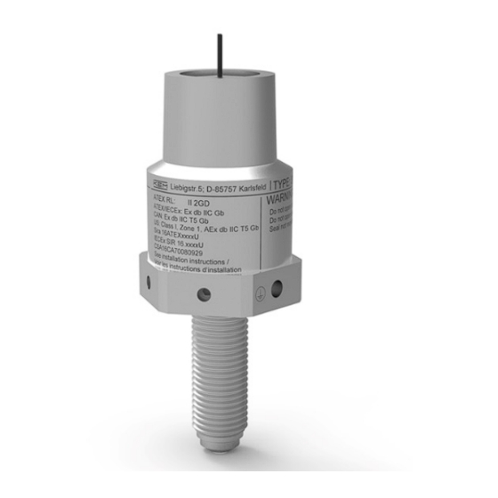
General Information General Information 1.1. Object and purpose The sensor adaptor will be the linking element between a flow meter and an encapsulated flameproof electronic. (EXd) A flow meter can be a gear meter, helical gear meter, turbines or others. Those have a sensor hole or a thread sleeve like it is defined in this document or mentioned in the attached drawings. -
Page 5: Safety Rules And Precautionary Measures
General Information 1.2.2. Safety rules and precautionary measures Following these instructions is mandatory. Modifications of the SV**-****-****-** implemented without preceding written consent from the manufacturer, will result in the immediate termination of product liability, warranty period and certification validity. Authorized technicians must carry out installation, use, maintenance and servicing of this equipment. Never open the housing in hazardous areas while connected to power supplying or consuming devices. -
Page 6: Ex Protection
= 0.11 W (Actively powered) 1.3.2. Ambient Temperature -40 °F to 185 °F [-40 °C to 85 °C] 1.3.3. Markings • KEM Küppers Elektromechanik GmbH Liebigstr. 5, D-85757 Karlsfeld Typcode: SV**-****-****-** • Labelling: • ATEX RL: 0123 Ex II 2G ATEX/IECEx: Ex db IIC Gb Amb. -
Page 7: Ordering Code
General Information 1.4. Ordering code Version: SV_M_EN_170515_E003... -
Page 8: Assembly
Assembly Assembly 2.1. Constituent parts Fig. 1: SV-Adaptor Assembly 2.2. Installing instructions First connect the two wires with the electronic device. Then mount the senor adaptor to the EX II 2GD electronic and tighten it with 32 Nm. Secure the assembly by a high temperature adhesive. As soon as this connection is solid the electronics can be assembled in the sensor hole or thread socket. -
Page 9: Dimensional Drawing
Assembly 2.3. Dimensional drawing Fig. 2: Dimensional drawing Sensor type Length T-K/I-K 1.57 in (40 mm) T-L/I-L 3.15 in (80 mm) 1.81 in (46 mm) 3.39 in (86 mm) Version: SV_M_EN_170515_E003... -
Page 10: Sensor Types
Assembly 2.4. Sensor types 2.4.1. Electrical Parameter of the Inductive Coil Wire diameter 60 µm Resistance Min. 70 Ω Inductance Max. 30 mH Coil supply Current < 200 µA Voltage < 5 V for Operational amplifier 2.4.2. Electrical Parameters of the carrier frequency coil Wire diameter 60 µm Resistance... -
Page 11: List Of Illustrations
Assembly 2.5. List of illustrations Fig. 1: Assembly with part numbering ........................8 Fig. 2: Dimensional drawing ............................ 9 Fig. 3: Grounding ..............................10 Version: SV_M_EN_170515_E003... - Page 12 T. +49 8131 59391-100 T. +49 9941 9423-37 F. +49 8131 92604 F. +49 9941 9423-24 sales@kem-kueppers.com service@kem-kueppers.com More distributors and partners can be found at: www.kem-kueppers.com Original KEM document: SV_M_EN_170515_E003 Copyright KEM, Subject to change without notice Version: SV_M_EN_170515_E003...