Table of Contents
Advertisement
Quick Links
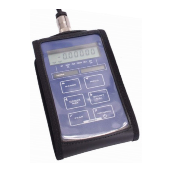
TR150
Portable Battery
Powered Indicator
Instruction Manual
UK / Europe Office
Tel: +44 (0)8700 434040
Fax: +44 (0)8700 434045
info@omniinstruments.co.uk
www.omniinstruments.co.uk
Australia / Asia Pacific Office
Tel +61 (0)282 442 363
Fax +61 (0)294 751 278
info@omniinstruments.com.au
www.omniinstruments.com.au
USA / Canada Office
Tel +1-866-849-3441
Fax +1-866-628-8055
info@omniinstruments.net
www.omniinstruments.net
Advertisement
Table of Contents

Related Manuals for Omni Instruments TR150


Summary of Contents for Omni Instruments TR150
- Page 1 TR150 Portable Battery Powered Indicator Instruction Manual UK / Europe Office Australia / Asia Pacific Office USA / Canada Office Tel: +44 (0)8700 434040 Tel +61 (0)282 442 363 Tel +1-866-849-3441 Fax: +44 (0)8700 434045 Fax +61 (0)294 751 278 Fax +1-866-628-8055 info@omniinstruments.co.uk...
-
Page 2: Table Of Contents
RS232 Port Connections ....................3 Internal Connections.....................3 MENU STRUCTURE......................5 CONFIGURATION MENU....................7 CALIBRATION MENU......................9 Operation Features ......................10 Normal Display Operation...................10 Switching the TR150 On/Off ..................10 RANGE Button ......................10 HOLD Button ......................11 GROSS/NET Button ....................11 SHUNT CAL Button ....................11 PEAK Button.......................11 TROUGH Button......................11 CONFIGURATION MENU Parameters ................12... -
Page 3: Introduction
Important Note The unit is supplied calibrated to a particular load cell. All user functions are available via the front keypad. Do not attempt to re-calibrate the TR150, unless you are authorised and have the equipment available to do so. -
Page 4: Electrical Connection Information
PIN 5 +ve Charge Input RS232 Port Connections If the TR150 has been ordered with the optional RS232 output, then this will be available via an 8 pin 723 series Binder connector. The wiring for this is detailed below:- PIN 1... - Page 5 There are six push buttons on the front panel of the TR150, which are available for use in normal operation. Each of these is described below:- Front Panel Function of Button in Normal Operation Mode Button button . To switch the TR150 ON or OFF press and hold the The RANGE button allows the user to toggle between two independent scales.
-
Page 6: Menu Structure
MENU STRUCTURE The TR150 has two menus, details of which are outlined below:- A CONFIGURATION MENU enables the user to tailor the operation to meet a specific application requirement. The values selected in the CONFIGURATION MENU are completely independent for each range. - Page 7 A CALIBRATION MENU is used to calibrate each of the two ranges with independent scales, as well as setting the display resolution for each range. SEnS 5.0 SEt rES 0000.000 CALibrAt LiVE? uSE SC? APPLY HI donE APPLY LO dISP LO 0000000 dISP HI 0000000...
-
Page 8: Configuration Menu
TO SKIP TO NEXT MENU ITEM PRESS TO SET OVERLOAD ALARM This allows the setting of a visual overload. The value entered is the display value at which the TR150 flashes OUErLOAd. OUEr Values between can be entered, using the... - Page 9 RS232 format are provided on page 13 of this manual. The RS232 rS232 output is an option that has to be ordered with the TR150. To conserve battery life, it is suggested that the RS232 output is disabled when it is not required.
-
Page 10: Calibration Menu
This allows the calibration engineer to change the sensitivity range of the TR150 when connecting to sensors with an output of greater than 5mV/V. The TR150 is factory set for 5mV/V. To ensure the unit is set to 5mV/V press SEnS 5.0 To select 50mV/V, you need to power down the unit and access the internal circuit board. -
Page 11: Operation Features
Operation Features Normal Display Operation The TR150 has a full 7 digit display, which can be scaled using the calibration menu to suit the application in which it is to be used. The display can show the instantaneous, peak or trough values. -
Page 12: Hold Button
GROSS/NET Button The gross/net button, when pressed, toggles between the gross and net display values. This enables the user to zero the display (by putting the TR150 into net mode) and show the change in readings from that point. This is useful for certain weighing applications where a tare weight exists, which can be removed by putting the TR150 into net mode. -
Page 13: Configuration Menu Parameters
Different values and settings are available for each RANGE. SEt OPEr Parameter The TR150 has a special power saving mode, which can be enabled or disabled within this parameter. When asked whether you wish to select , pressing will put the TR150 P SAvE? into power save mode for the RANGE selected. - Page 14 The benefit is that the battery life, based on a 350Ω sensor bridge being connected, increases from 45 hours to 450 hours. It is also important to remember that when the TR150 is re-calibrated with a sensor, the power save facility will be automatically turned off. If required, the power save facility will therefore need to be re-activated after calibration has been completed.
-
Page 15: Calibration Menu Parameters
TR150, it will be necessary to gain access to the internal PCB (you must turn the TR150 off) to move link LK1 to JP1 (see picture below). This will allow the TR150 to accept signals of up to 50mV/V. -
Page 16: Calibration Procedures
LiVE the sensor signal at two calibration points and scales the TR150 automatically. If this is not possible, then the sensitivity figure (in mV/V) from the sensor calibration certificate can be used to scale the TR150, by using the calibration. - Page 17 Press to return the TR150 to normal operation mode, with the new calibration data stored. If you see FaiLEd, then you will need to repeat the calibration, checking that you have completed the procedure in the correct order, and that the sensor is connected correctly.
-
Page 18: Specifications
1 part in 65,000 at 10Hz update rate Annunciators: Low Battery warning; peak; trough; hold; net; shunt cal; range Tactile Keys with recessed rims for:- ON/OFF Switches TR150 power on/off RANGE Selects between two ranges HOLD Hold the current display value, press again to release...
Need help?
Do you have a question about the TR150 and is the answer not in the manual?
Questions and answers