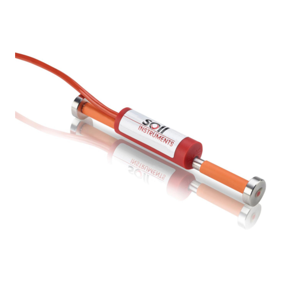
Summary of Contents for Soil Instruments 1030
- Page 1 Vibrating Wire Embedment Strain Gauge User Manual Man142 6.1.0 06/08/14 P. Day Andy Small Chris Rasmussen Manual No. Revision Date Originator Checked Authorised for Issue User Manual...
-
Page 2: Table Of Contents
Contents Section 1 : Introduction ..........................3 Section 2 : Equipment Supplied ........................4 Section 3 : Installation ........................... 5 3.01 Installation in Concrete ........................ 5 3.02 Installation in Pre-cast blocks ..................... 7 Section 4 : Protection of the Installation ....................8 Section 5 : Cable Routing and Protection .................... -
Page 3: Introduction
Section 1 : Introduction Embedment Strain Gauges were developed by the British Transport & Road Research Laboratory to measure the internal strain in concrete structures. These waterproof gauges were developed in conjunction with Imperial College, London and incorporate the latest materials and techniques to make these gauges suitable for use in hostile conditions. -
Page 4: Equipment Supplied
Each gauge is supplied with a thick walled silicon rubber sleeve over each barrel (see Figure1) to protect the gauge barrel when it is tied to support bars during mounting. Although gauges are checked prior to leaving Soil Instruments, damage can occur during transit. It is suggested that the gauges are visually checked immediately upon receipt. -
Page 5: Installation
Section 3 : Installation The gauges are supplied sealed and pre-tensioned; no adjustment is necessary or possible. It is good practice to connect a readout to the gauge and ensure that the reading in free-air is stable and around the mid-range position. Gentle pressure applied to the gauge ends (i.e. small compression) should cause the F²/1000 reading to decrease. - Page 6 Above; soft iron wire used to secure the gauge between reinforcing bars, Plan View. As an alternative to the above, small rebar sections, cut to length can be used to replace the soft steel wire with cable ties attaching these short lengths to the gauge and the main rebar. If this method is selected under no circumstances over tighten the cable ties so that no movement is allowed.
-
Page 7: Installation In Pre-Cast Blocks
3.02 Installation in Pre-cast blocks An alternative to fixing to rebar, is to pre-cast the gauge into a block of concrete prior to this being cast into the main concrete pour. This method takes more time, but does protect the gauges better during the main pour. -
Page 8: Protection Of The Installation
Section 4 : Protection of the Installation All efforts must be taken to protect the gauge during concreting without significantly altering the reinforcement performance. Where the gauge is installed in a vulnerable position good practice is to spray the area with marker paint as a warning and/or cover the area with fine wire mesh. -
Page 9: Cable Routing And Protection
Section 5 : Cable Routing and Protection Having established and marked the preferred route of the cables and decided upon the type of cabling arrangement to be adopted, begin running the cables from the gauges furthest from the readout location. Where cables are not to be ducted, they should be strapped to the reinforcement, in a position where they are least likely to be damaged, using strong tape or cable ties. -
Page 10: Monitoring
Units. The required format should be established prior to any test beginning and remain consistent for the duration of the monitoring program. The Soil Instruments Model 1030 & 1050 Readout/Loggers requires the Base reading to be recorded in Period units for automatic calculation of the applicable Engineering units. (See the Readout/Logger Operation Manual for full details). -
Page 11: Data Interpretation
Section 7 : Data Interpretation Data from strain gauges is generally presented in micro strain where strain is the ratio of the change in length per unit length:- Practical K factor = 34080 (Gauge calibration constant) Conversion of Period and Linear Units to micro-strain is carried out using either of the formulae detailed below;... - Page 12 Force (F) = Stress (S) x Area (A) Where A = Cross sectional area in m² Where F units = Newton’s Where S units = N/m² Stress (S) = Young Modulus of Elasticity (E) x Strain ( ) Where E units = N/m² Example calculation Steel pipe outside diameter = 1.016m Steel pipe inside diameter = 0.984m...
-
Page 13: Temperature Effects
Section 8 : Temperature Effects The curing of concrete can generate large temperature changes. It is therefore best practice to record temperature when you record strain readings. You can then use the temperature data as well as strain data to analyse the behaviour of the structure. -
Page 14: Troubleshooting Guide
Another readout unit should be used to check the readings from the transducers and Soil Instruments Ltd should be consulted about the faulty readout unit. Before proceeding to Steps 2 and 3, if possible the continuity should be checked between conductors and earthing screen of the electrical cable. -
Page 15: Appendix A. Vibrating Wire Data
Appendix A. Vibrating Wire Data Frequency Units (f): The tension of a wire can be measured by registering the frequency (note) at which it naturally vibrates. If the wire is "plucked" electronically the frequency at which it vibrates can be measured. -
Page 16: Appendix B. Troubleshooting Flowchart
(See step 4) It must be suspected that the portable A faulty instrument is Is reading OK with logger used first is possible. Contact alternative logger? faulty. Contact Soil Instruments Ltd. Soil Instruments Ltd. User Manual... -
Page 17: Appendix C. Ce Declaration
Appendix C. CE Declaration User Manual... - Page 18 User Manual...
- Page 19 User Manual...
- Page 20 Bell Lane, Uckfield, East Sussex TN22 1QL, United Kingdom +44 (0) 1825 765044 info@soilinstruments.com www.soilinstruments.com Soil Instruments Ltd. Registered in England. Number: 07960087. Registered Office: 3rd Floor, Ashley Road, Altrincham, Cheshire, WA14 2DT User Manual...


Need help?
Do you have a question about the 1030 and is the answer not in the manual?
Questions and answers