Table of Contents
Advertisement
Quick Links
Advertisement
Table of Contents

Related Manuals for Iradion Infinity Series


Summary of Contents for Iradion Infinity Series
- Page 1 OPERATOR’S MANUAL RS232 Interface http://www.iradionlaser.com...
-
Page 2: Table Of Contents
Table of Contents Overview ........................ 2 Equipment Required ....................2 Using the Software ....................5 LC Command Packets Listing ................9 Serial Data Format....................9 Command Packet Format ..................9 Packet Characters: ....................9 Check Character Calculation .................. 9 Command Response: .................... 9 Response Packet Format .................. -
Page 3: Overview
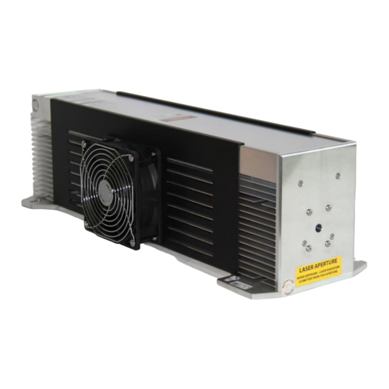
1. Overview Iradion Infinity Series lasers offer to the user the ability to communicate with the laser using RS232 communication. The RS232 communication signals are available on one of the two ports on the rear-side of the laser: J7 HD-15 style, or J8 RJ45 style. -
Page 4: Figure 1 Setup Wizard To Start Installation
Figure 1 Setup Wizard to start installation. Figure 2 select installation destination Figure 3 Confirm installation... -
Page 5: Figure 4 Complete Installation
Figure 4 Complete installation Figure 5 Desktop Icon... -
Page 6: Using The Software
4. Using the Software 4.1. Confirm the serial port on the windows PC is functional. 4.2. Connect the serial port (PC) to the IRADION CO2 laser’s serial port using appropriate cabling. Refer to IRADION LASER user guide on how to connect the cabling. - Page 7 4.10. If the communication to the laser is successful, the application will start filling in following information boxes by polling the laser: • Laser state. • Simmer duty • Pulse stretch • Temp • Interlock • Temp Warning • Laser fault •...
-
Page 8: Figure 6 Comm Writer Ii Startup View
Comm port combo box Initialize Send Comm Port Command Button Status Lights Command Green = ON Window Read= OFF/Flt Status Results Serial Results Comm Port Connection Close Get Option Selected TRUE=Connected Application Results FALSE=NOT Connected Figure 6 Comm Writer II startup view Selected comm port... -
Page 9: Figure 8 Comm Writer Connected State View
Grayed Send command out=Connected button is enabled because connection is true. Connected Port Command windows is filled with available commands. Set Figure 8 Comm writer connected state view Auto Fan Enable is Connection Failure Communication failed. Click YES to reset the application or NO to exit the application. -
Page 10: Lc Command Packets Listing
4.1 This section describes the packet protocol for transmitting and receiving data via the RS232 com line to the Iradion Laser Controller Card. 4.2 Note: The Iradion Controller Card is programmed to reply only when queried and does not automatically transmit strings. -
Page 11: Response Packet Format
11. Response Packet Format 11.1. The response packet is made up of ascii text characters as described below. Start Length Data Data End Check 12. Packet Characters: Start # character. 2 characters, ascii hex format 00 – FF. Length * 2 characters, ascii hex format 00 – 0 to n characters, ascii hex format 000000…N –... - Page 12 P2 = CPLD ID—A2 P3 = Simmer Frequency byte – 0x31 to 0xC7 200 KHz to 50 KHz, 5 KHz steps P4 = Simmer Duty Cycle byte – 0x00 to 0x14 0 to 20%, 1% steps P5 = Pulse Stretch byte – 0x00 to 0x64 0 to 10 us, 1 us step P6 = Get Temp.
- Page 13 Response Packet 0x20 (Get Laser Serial Number Command) Packet Length—0x01 to 0xFF. (See above Packet Characters for description) p1 = Laser Serial # - 2 bytes – 0x0001 to 0xFFFF p2 = Laser Set Voltage 2 bytes 0x0001 to 0xFFFF p3 = Laser Power Rating byte - 0x01 to 0xFF p4 = Laser Power Measured byte - 0x01 to 0xFF p5 = Auto-Fan Enable byte –...
- Page 14 p4) Laser Power Measured: Retrieving Laser Power measured is part of the “Get Laser Serial Number Command” code. This Command will return a p4 Packet; this byte will return a value between 0x00 and 0xFF. This is the actual laser output power measured during the final testing procedure.
- Page 15 Command Function Data Set Auto-Fan Enable 0x16 p5 = Auto-Fan Enable byte-(0x01)ex Response Packet 0x16 Same as Get Laser Serial Number Response Packet Set Auto-Fan Disable 0x16 p5 = Auto-Fan Disable byte-(0x00) Response Packet 0x16 Same as Get Laser Serial Number Response Packet Command Function Data Get Options...
-
Page 16: The Command Functions List
13. The Command Functions list Get Status $100A&1C Get Options $180A&24 Get Laser Serial Number $200A&1D Set Laser On Time $1712XXXXXXXX &XX Set Auto Fan Enable $160C01&85 Set Auto Fan Disable $160C00&84 Set Mod Low Grounded $150C01&84 Set Mod Low Not Grounded $150C00&83 Set Keylock Switch Enable $210C01&81... - Page 17 Set Simmer Frequency 165 $110C3C&95 Set Simmer Frequency 170 $110C3A&93 Set Simmer Frequency 175 $110C38&8A Set Simmer Frequency 180 $110C37&89 Set Simmer Frequency 185 $110C35&87 Set Simmer Frequency 190 $110C34&86 Set Simmer Frequency 195 $110C32&84 Set Simmer Frequency 200 $110C31&83 Set Simmer Duty Cycle 0% $120C00&80...
- Page 18 Set Pulse Stretch 8 us $130C50&86 Set Pulse Stretch 9 us $130C5A&97 Set Pulse Stretch 10 us $130C64&8B Iradion Laser, Inc, Patents: US 7460577 B2 One Technology Drive US 8295319 B2 Uxbridge, MA, 01569 P/N: 92-3006_Rev.A 8-2022 Ph:1 (401) 762-5100...
Need help?
Do you have a question about the Infinity Series and is the answer not in the manual?
Questions and answers