
Related Manuals for Mecon RE 250


Summary of Contents for Mecon RE 250
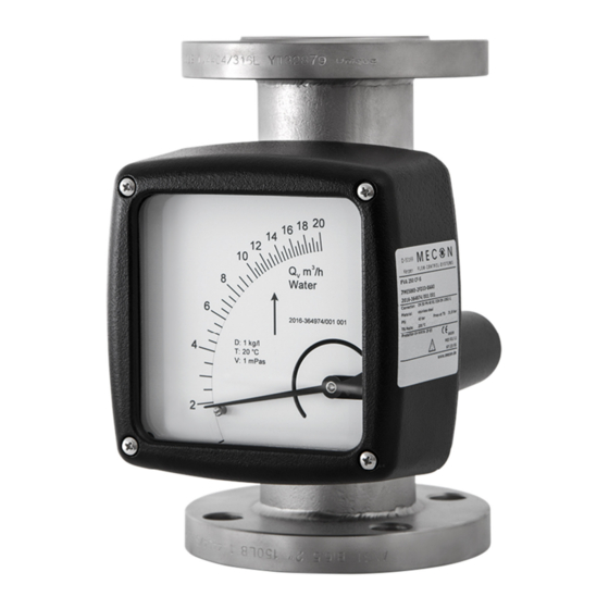
- Page 1 RE 250 Variable Area Flowmeter Operating Instructions © MECON GmbH BA / RE 250 / EN / V17-11...
- Page 2 All rights reserved. It is prohibited to reproduce this document, or any parts thereof, without prior written authorization of MECON GmbH. Subject to change without notice. Copyright 2017 by MECON GmbH - Röntgenstraße 105 - 50169 Kerpen - Germany Page 2 / 32 www.mecon.de BA / RE 250 / EN / V17-11...
-
Page 3: Table Of Contents
6 Description code _________________________________________________________ 17 7 Technical Data ___________________________________________________________ 21 7.1 Pressure limits vs. temperature stainless steel ___________________________________ 23 7.2 Dimensions and weights ____________________________________________________ 24 8 Electrical connections _____________________________________________________ 28 BA / RE 250 / EN / V17-11 www.mecon.de Page 3 / 32... -
Page 4: Safety Instructions
1 Safety Instructions 1.1 Intended use The series RE 250 of flowmeters with a standard length of 250 mm (9.84 inch) and a completely metal design is suitable for measuring different liquids and gases in closed piping. The robust design enables the operation in rough conditions. Different types of flanges, liners and float materials meet the requirements of the pharmaceutical and chemical industries. -
Page 5: Certifications
Safety Instructions 1.2 Certifications CE marking The manufacturer certifies for the device RE 250 meets all statutory requirements of the following EC directives by applying the CE marking: • Pressure equipment directive 2014/68/EU • Low voltage directive 2014/35/EU * •... -
Page 6: Start-Up
● possibility of shock pressure in the piping, e.g. due to rapid throttling or process shut-off ● turbulence, pulsations, etc. which could lead to vibrations of the flowmeter ● rapid pressure build-up in the piping Page 6 / 32 www.mecon.de BA / RE 250 / EN / V17-11... -
Page 7: Device With Electrical Output (Mem)
● Move the pointer to the desired position. ● Tighten the screws to fix the pointer. 1 Limit pointer 2 Fixing screw Fig. 2 Adjustment of the switching point (limit switch) BA / RE 250 / EN / V17-11 www.mecon.de Page 7 / 32... -
Page 8: Installation Mode Of Operation
The distance can be reduced by mounting the devices staggered by the length of one device. To eliminate doubt the influence can be tested by moving the instrument up and down Page 8 / 32 www.mecon.de BA / RE 250 / EN / V17-11... - Page 9 ● Ensure that the operating pressure for the flowmeter corresponds to the calibration reference pressure to avoid erroneous measurements. Tightening torques The flange bolts for devices with PTFE liner may be tightened with the following torques (acc. guideline VDI/VDE 3513): BA / RE 250 / EN / V17-11 www.mecon.de Page 9 / 32...
-
Page 10: Operating Principle
This kind of filter is also recommended if such particles cannot be avoided in standard operation. Operating principle Like other devices of this series the variable area flowmeter RE 250 operates according to the principle of flotation: The measuring unit consists of a metal tube with a measuring ring in which a float can move up and down. -
Page 11: Service
For a detailed inspection and cleaning the device must be removed from the piping. Caution! Appropriate safety precautions have to be taken when removing the device. Always use new gaskets when reinstalling the device in the piping. BA / RE 250 / EN / V17-11 www.mecon.de Page 11 / 32... -
Page 12: Replacing Float
0.15 – 1.5 m³/h) cannot be done by the customer. The device has to be returned to the manufacturer. For details please refer to chapter “6.4 Returning the device to the manufacturer”. Page 12 / 32 www.mecon.de BA / RE 250 / EN / V17-11... -
Page 13: Returning The Device To The Manufacturer
For reasons of environmental protection and safeguarding the health and safety of our personnel all devices sent to MECON GmbH to be repaired must be free of toxic and hazardous substances. This also applies to cavities of the devices. -
Page 14: Device Description
Standard device with display unit made of aluminium The measurement range is indicated directly on the scale. The equipment can be supplied with auxiliary electrical components and touch-sensitive switches for process monitoring and control. Page 14 / 32 www.mecon.de BA / RE 250 / EN / V17-11... - Page 15 Heating shield Fig. 8 Device with heating sheath For installations where temperature drops are unacceptable the devices are available with an external heating shield. BA / RE 250 / EN / V17-11 www.mecon.de Page 15 / 32...
-
Page 16: Nameplate
Please refer to the device nameplate to ensure that the device is built according to your order. Check particularly for the correct supply voltage. Fig. 9 Nameplate of the RE 250 Page 16 / 32 www.mecon.de BA / RE 250 / EN / V17-11... -
Page 17: Description Code
Form RF (ASME B16.5) ½ ” – 6 ” Form FF (ASME B16.5) ½ ” – 6 ” Form RTJ (ASME B16.5) 1 ” – 6 ” BA / RE 250 / EN / V17-11 www.mecon.de Page 17 / 32... - Page 18 Air (T = 0 °C, pe = 0 bar, η= 0.0181 mPa s, ρ = 1,293 kg/m³) Specify in plain text Float damping Without float damping With float damping Page 18 / 32 www.mecon.de BA / RE 250 / EN / V17-11...
- Page 19 Water (η= 1 mPa s, ρ = 1 kg/l) Air (T = 0 °C, pe = 0 bar, η= 0.0181 mPa s, ρ = 1,293 kg/m³) Specify in plain text BA / RE 250 / EN / V17-11 www.mecon.de Page 19 / 32...
- Page 20 Cardboard plate with a cable tie Stainless steel plate (dimensions 70 x 30mm) Cardboard plate with cable tie + stainless steel plate (dimensions 70 x 30 mm) Page 20 / 32 www.mecon.de BA / RE 250 / EN / V17-11...
-
Page 21: Technical Data
Weatherproof and/or non heated locations Class C in accordance with DIN IEC 654 Section 1 Protection class (DIN EN 60529) Display unit made of aluminium: IP65 made of stainless steel: IP66 BA / RE 250 / EN / V17-11 www.mecon.de Page 21 / 32... - Page 22 = (U - 14V) / 22 mA Temperature influence < 10 µA / K ® RE 250 with current output 4 … 20 mA and HART -Protokoll + digital output Switching function NAMUR (EN 60947-5-6:2000) Max. voltage 30 V DC Max.
-
Page 23: Pressure Limits Vs. Temperature Stainless Steel
Technical Data Pressure limits vs. temperature stainless steel Fig. 10 Maximum Pressure PS vs. temperature TS BA / RE 250 / EN / V17-11 www.mecon.de Page 23 / 32... -
Page 24: Dimensions And Weights
(4,92) (4,96) 22,0 (48,4) 6” (4,92) (4,96) 25,0 (55,0) All Dimensions in mm (inch) weights in kg (lbs) * For dimension L please refer to page 27. Page 24 / 32 www.mecon.de BA / RE 250 / EN / V17-11... - Page 25 125 (4,92) 126 (4,96) 175 (6,89) 120 (4,72) 29,0 (63,8) All Dimensions in mm (inch) weights in kg (lbs) * For dimension L please refer to page 27. BA / RE 250 / EN / V17-11 www.mecon.de Page 25 / 32...
- Page 26 All Dimensions in mm (inch) weights in kg (lbs) For dimension L please refer to page 27. Dimension will be 258 mm for version with displaced display unit Page 26 / 32 www.mecon.de BA / RE 250 / EN / V17-11...
- Page 27 Devices with threaded connection: Mounting dimension L: 300 mm Special feature ANSI B16.5 ½“ for measuring tube B (measuring range end value 1000 /1600 /2500 /4000 l/h): BA / RE 250 / EN / V17-11 www.mecon.de Page 27 / 32...
-
Page 28: Electrical Connections
Electrical connections The display lid can be removed by loosening the four mounting screws at the front. Insert the connection cable through the cable gland at the baseplate. The RE 250 is equipped with screw terminals. Limit switches Fig. - Page 29 Electrical Connections Fig. 14 Connection diagram for RE 250 with two limit switches Current output (MEM) Fig. 15 Terminals (current output) Fig. 16 Terminals (with add. digital outputs) Fig. 17 Connection diagram for transducer MEM with current output BA / RE 250 / EN / V17-11 www.mecon.de...
- Page 30 Current output with digital outputs (MEM) Fig. 18 Connection diagram for transducer MEM with 2 limit switches Fig. 19 Connection diagram for transducer MEM with limit switch and pulse output Page 30 / 32 www.mecon.de BA / RE 250 / EN / V17-11...
- Page 31 Electrical Connections Current output with HART Protocol (MEM) ® ® Abb.20 Connecting terminal of the RE 250 with current output and HART -Protocol (MEM) ® Abb.21 Wiring diagram fort he transmitter with current output and HART -Protocol (MEM) Protection class The protection class of the display unit made of aluminium is class IP65.
- Page 32 MECON GmbH Röntgenstr. 105 50169 Kerpen / Germany Tel.: +49 (0)2237 600 06 – 0 Fax.: +49 (0)2237 600 06 – 40 Email: info@mecon.de www.mecon.de OI_RE 250_EN Subject to change without notice Copyright ©...
Need help?
Do you have a question about the RE 250 and is the answer not in the manual?
Questions and answers