Advertisement
Quick Links
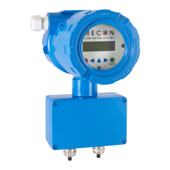
Fig 1
Transmitter max-flux M1
__
Application domain
The mag-flux M1 is a microprocessor controlled and program-
mable transmitter that can be customized using control unit.
Although
basic
configuration
calibration are realized at the factory, other settings such as
those for measurement data processing, analysis, display and
output are user definable.
Measurement data from sensors of series mag-flux are processed
by the transmitter (hereinafter referred to as mag-flux M1). It
can be installed directly on the sensor (compact version) or be
mounted separately (remote version) and it is designed for flow
velocities up to 10 m/s.
A remote version is available for sensor mag-flux A, mag-flux S,
mag-flux F5 and also for probes mag-flux MIS 1/D and mag-flux
MIS 2/15.
A compact version is only available for sensor mag-flux A and
mag-flux S.
The transmitter mag-flux M1 is communication enabled and
®
supports optional the HART
protocol.
__
Special features
•
High-speed signal processing by 16-bit Microcontroller
•
Easy multilingual menu navigation with a two-line display
•
Self-monitoring system
•
Internal simulation for all output values
•
Analog output (0/4-20 mA)
•
Digital outputs (pulse, frequency, alarm, forward and
reverse flow, MIN / MAX flow rate)
•
User settings protected by user definable password
Mecon GmbH
Phone +49(0)2237 600 06 - 0
Röntgenstraße 105
D-50169 Kerpen
settings
such
as
transmitter
www.mecon.de
WWW.TEESING.COM | +31 70 413 07 50
Transmitter mag-flux M1
__
Introduction
I.
Shipping, storage and product inspection
Shipping and storage
The device is to be safeguarded against dampness, dirt, impact
and damage.
Product inspection
Upon receipt of the product, check the contents of the box and
the product particulars against the information on the delivery
slip and order form so as to ensure that all ordered components
have
been
supplied.
Notify
immediately upon receipt of the product. Any damage claim
received at a later time will not be honored.
II.
Warranty
Your flowmeter was manufactured in accordance with the highest
quality standards and was thoroughly tested prior to shipment.
However, in the event any problem arises with your device, we
will be happy to resolve the problem for you as quickly as
possible under the terms of the warranty which can be found in
the terms and conditions of delivery. Your warranty will only be
honored if the device was installed and operated in accordance
with
the
instructions
for
commissioning and/or maintenance work is to be carried out by
qualified and authorized technicians only.
III. Repair
It is important that you do the following before shipping your
flowmeter to MECON GmbH for repair:
•
Enclose a description of the problem with your device.
Describe in as much detail as possible the application and
the physical and chemical properties of the fluid.
•
Remove any residues from the device and be sure to clean
the
seal
grooves
and
particularly important if the fluid is corrosive, toxic,
carcinogenic, radioactive or otherwise hazardous.
•
The operator is liable for any substance removal or personal
damage costs arising from inadequate cleaning of a device
that is sent for repair.
®
IV. Using HART
hand-held terminal
For information regarding operation of the transmitter using the
HART
hand-held terminal, see "Operation of the mag-flux M1
transmitter using the HART
hand-held terminal."
__
Steps prior to operation
It is essential that these operating instruc-
tions have been read before installing and
operating the device. The device has to be in-
stalled and serviced by a qualified technician
only. The mag-flux M1 transmitter is solely
suitable to measure volume flow of liquids in
conjunction with a sensor of series mag-flux.
Downloading of the present document from our web site
www.mecon.de
and printing out this document is allowed only for
purposes of using our flowmeters. All rights reserved. No instruc-
tions, wiring diagrams, and/or supplied software, or any portion
thereof, may be produced, stored, in a retrieval system or
transmitted by any means, electronic, mechanical, photocopying
or otherwise, without the prior written permission of MECON
GmbH.
Although the materials in the present document were prepared
with extreme care, errors cannot be ruled out. Hence, neither the
Fax +49(0)2237 600 06 - 40
customerservice@mecon.de
us
of
any
shipping
damage
your
device.
Any
mounting,
recesses
thoroughly.
This
Page 1 / 35
Mecon 10/2014
is
Advertisement

Related Manuals for Mecon mag-flux M1


Summary of Contents for Mecon mag-flux M1
-
Page 1: Special Features
Measurement data from sensors of series mag-flux are processed by the transmitter (hereinafter referred to as mag-flux M1). It • The operator is liable for any substance removal or personal... - Page 2 MECON GmbH accepts no liability for any loss or damage of any kind arising from improper operation of any product, Mecon GmbH improper handling or use of any replacement part, or from Dept.
- Page 3 Transmitter for magnetic-inductive flowmeters series mag-flux Note! In order for the device to perform correctly and Product name Transmitter Type mag-flux M1 safely, it must be shipped, stored, set up, mounted Version-No. 10/2014 dated from 2014-10-06 operated and maintained properly.
- Page 4 System design The complete meter consists of a mag-flux M1 transmitter and a sensor e.g. mag-flux series. The device is qualified to measure any liquid, conductive media, providing that the sensor’s material is suitable for the fluid.
- Page 5 DIL-8 housing, located in a socket on the power supply board. It includes all characteristic data of the sensor e.g. sensor constant, Additionally the mag-flux M1 has a LCD display with backlight. version or serial number. Consequently, the memory module is...
- Page 6 - MIN flow rate used, can be found on the relevant data sheet or rating plate. - MAX flow rate Operating the mag-flux flow probes with the mag-flux M1 - alarm The flow probes mag-flux MIS 1/D und mag-flux MIS 2/15 are •...
-
Page 7: Technical Data
Degree of protection IP67. Fig 5 Proper installation of cables at high humidity and wet conditions The mag-flux M1 transmitter has to be mounted free of vibra- tions! Mecon GmbH Phone +49(0)2237 600 06 - 0 Fax +49(0)2237 600 06 - 40 Page 7 / 35 Röntgenstraße 105... - Page 8 The data sheet/rating plate of the connected sensor is binding. Empty pipe detection All transmitters mag-flux M1 have a selectable empty pipe detec- tion. The operating reliability depends on the conductivity of the liquid and the cleanliness of the electrodes.
- Page 9 • A load at least 250 Ω must exist in the signal circuit for error ® free communication via the HART protocol. Fig 8 Electrical connections of the transmitter mag-flux M1 Fig 10 Mains and signal terminals of the transmitter mag-flux M1 Terminal Label...
- Page 10 Feed the electrode line through the left gland and the magnetic current line through the right gland and connect the cables as shown in Figure 12. Fig 11 Connection diagram for sensor cable of the mag-flux M1 Terminal Function Fig 12 Electrical connections of the mag-flux A sensor...
- Page 11 Transmitter mag-flux M1 Connection of the sensor mag-flux S and the flow probes Changing the direction of the transmitter housing (only mag-flux MIS compact version) For the compact version the transmitter housing isn't rigid inter- These sensors are equipped with a pre-assembled cable ex- linked with the sensor housing but it can be turned by ±...
- Page 12 The board can be removed after loosening the 3 fixing screws (refer Fig 17). Display The control unit in the mag-flux M1 has an integrated back lighted, alphanumeric display with two 16-character lines (format 16 x 60 mm). Measurement data and settings can be read direct- ly from this display.
- Page 13 Transmitter mag-flux M1 Operating modes Keys and their functions On the control unit are six keys to change the settings. The transmitter mag-flux M1 can be operated in the following modes: Note! Mode 1: Display Do not press these keys with sharp or sharp-edged...
- Page 14 A two level protection is implemented for the mag-flux M1. Entering the customer password will allow all changes that are The control unit of the transmitter mag-flux M1 has an alphanu- permissible for customers. This password can be changed when meric display with two lines.
- Page 15 Transmitter mag-flux M1 mag-flux M1 transmitter functions The software functions of the mag-flux M1 transmitter are separated into functional classes which are arranged in a circle. Navigation is carried out by using the 3 or 4cursor keys. To return to your starting point (the MEASURED VALUES functional class) press Esc.
- Page 16 Transmitter mag-flux M1 Volume flow rate Functional class: MEASURED VALUES If you select the function volume flow the current value for the The MEASURED VALUES functional class includes all functions for volume flow will be displayed: displaying the measured values.
- Page 17 Transmitter mag-flux M1 The average velocity is calculated from the measured volume QV + flow velocity flow and the cross section of the meter tube. For the calculation If the function QV + flow velocity is selected, in the first line...
- Page 18 Transmitter mag-flux M1 If the entered password is not correct, the following message will Functional class: PASSWORD be displayed: The PASSWORD functional class includes the functions for ente- ring and changing the customer password and entering the ser- Password vice password.
- Page 19 When the unit is changed, the totalizers will be reset to 0.00 automatically! Totalizer reset The transmitter mag-flux M1 has three independent totalizers. Each of them can be reset individually to the initial value 0.00. In the first step the required totalizer has to be choosen by using the 5 or 6 key.
- Page 20 Transmitter mag-flux M1 Low flow cut Functional class: MEASUREMENT PROCESSING The low flow cut is a threshold for flow rate (percentage the The MEASUREMENT PROCESSING functional class includes all upper-range value). functions that affect the processing of the measured values.
- Page 21 Scaling the outputs of the mag-flux M1 The measuring variable volume flow rate is shown by the trans- mitter mag-flux M1 as well as an analog current output as a pulse output. The correlation of output and flow rate is not fixed but it can be defined by the parameters QV LRV und QV URV (see Fig 28).
- Page 22 After choosing the function QV limit hysteresis and pressing the ↵-key, the following selection field will be displayed Example: Limit value messages of the mag-flux M1 Qv limit hysteresis 00 % The hysteresis of the QV limiting values can be set in 1-percent increments from 0 to 10 %.
- Page 23 Transmitter mag-flux M1 Pulse output unit Functional class: PULSE OUTPUT The parameter pulse output unit is of relevance only, if the The PULSE OUTPUT functional class includes the functions regar- parameter output of pulses or frequency is set to „pulses“.
- Page 24 Transmitter mag-flux M1 Status output assignment Functional class: STATUS OUTPUT This function allows the operator to define the event assignment The functional class STATUS OUTPUT includes the functions for for the status output. The most common setting is the reverse setting the status output.
- Page 25 Transmitter mag-flux M1 The range from 4 to 20,5 mA is according to the NAMUR-recom- Functional class: CURRENT OUTPUT mendation and uses the measuring range up 104%. The CURRENT OUTPUT functional class includes the settings for the current outputs of the transmitter.
- Page 26 Transmitter mag-flux M1 Simulation on / off Functional class: SIMULATION The function Simulation on/off is intended for activating or de- The functional class SIMULATION includes the functions for simu- activating simulation mode. lating output signals or output states. For selecting the desired function please use the key 5 or 6.
- Page 27 Transmitter mag-flux M1 Simulation preset Qabs Direct simulation of outputs – current output This parameter is of relevance only, if the parameter preset of This parameter is of relevance only, if the parameter preset of is set to „QVabs“. is set to „direct“.
- Page 28 Transmitter mag-flux M1 Functional class: SELF-TEST Self-test period (STP) This parameter is of relevance only, if the parameter Self-test The function class SELF-TEST includes all functions relating to the is set to „on“. self-test of the sensor. Using this function the time gap for the periodical measurement The diagnostic functions of the transmitter, which monitor the of the field coil current is defined.
- Page 29 Transmitter mag-flux M1 Empty pipe detection on / off The function Empty pipe detection on / off, is used for en- abling or disabling the continuous empty pipe detection. After selecting this function by the use of key 5 or 6 and pressing ↵, the following selection field will be displayed:...
- Page 30 This functional class SETTINGS SENSOR + M1 includes the characteristic value for the sensor. general settings for the transmitter mag-flux M1. The value for CFH must be entered to ensure a correct measure- ment. It will be found on the rating plate of the sensor.
- Page 31 Language 6 and pressing ↵, the current setting will be displayed. When using the control unit, different languages are available for the user guidance of the mag-flux M1. Example: The function Language is intended for setting the language. Flow direction The settings English and German are available.
-
Page 32: Error Messages
Enhanced version with LC-Display After choosing the desired function using the key 5 or 6 and pressing ↵, the software version will be displayed: The integrated diagnostic system of the transmitter mag-flux M1 distinguishes between two types of errors (see also Section Example: „Transmitter error messages”). - Page 33 The data memory module (DSM) with the Insert the data storage module (DSM) in the socket on calibration data sensor the power supply board of the mag-flux M1. customer-specific settings of the transmitter is missing. Information: Error message: “Parameter is inconsistent” (system error 0x0400)? To recall a list of all inconsistencies, first enter a valid password and immediately an invalid password.
- Page 34 Transmitter mag-flux M1 System error messages System errors will be displayed starting with the message “system error” followed by a 5-digit number in hexadecimal code. The error codes are explained in the following table: Description Error code Beschreibung System errorExtEEProm 0x00002...
- Page 35 Transmitter mag-flux M1 Declaration of Decontamination (can also be downloaded from www.mecon.de/en/Declaration/Decontamination.pdf) Dear customer, because of legal regulations and for the safety of our employees and operating equipment, we need the „Declaration of Decontamination“ with your signature, before your order can be handeled.
Need help?
Do you have a question about the mag-flux M1 and is the answer not in the manual?
Questions and answers