
Related Manuals for Trio MC6N-ECAT


Summary of Contents for Trio MC6N-ECAT
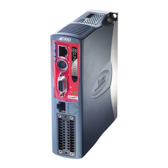
- Page 1 ETHECAT PORT FLEXIBLE AXIS PORT CHASSIS EARTH BACKLIT DISPLAY SCREW RS232 / RS485 PORT STATUS LEDS PROGRAMMING PORT POWER - I/O - WDOG CANBUS & SD CARD QUICK START GUIDE MC6N-ECAT P960 - P965...
-
Page 2: Safety Warning
SAFETY WARNING During the installation or use of control systems, users of Trio products must ensure that there is no possibility of injury to any person or damage to machinery. Control systems, especially during installation, can malfunction or behave unexpectedly. Bearing this in mind, users must ensure that even in the event of a malfunction or unexpected behaviour, the safety of an operator or programmer is never compromised. - Page 3 A standard Ethernet connector is provided for use as the primary programming interface. The Trio programming software, Motion Perfect 4.3 and above, must be installed on a Windows based PC that is fitted with an Ethernet connection. The IP address is displayed on the MC6N display for a few seconds after power-up or when an Ethernet cable is plugged in.
- Page 4 SERIAL CONNECTIONS (8 WAY MINI-DIN) Function Note RS485 Data In A Rx+ Serial Port #2 RS485 Data In B Rx- RS232 Transmit Serial Port #1 0V Serial RS232 Receive Serial Port #1 5V Output 150mA max* RS485 Data Out Z Tx- Serial Port #2 RS485 Data Out Y Tx+ * Current shared with encoder port...
- Page 5 SHIELDING THE FLEXIBLE AXIS PORT SHIELD SCREW Ensure that: 1. The shield screw is grounded as close to the MC6N as possible. ENCODER INPUT (9 WAY D-TYPE) 2. 0V connection is NOT used for terminating screens. Enc 0V 3. Pin 5 of Encoder/Stepper plug is connected to 0V on drive. 4.
- Page 6 I/O CONNECTOR Not Used Enable (Watchdog) Not Used I/O 8 Input 0 I/O 9 Input 1 Input 2 I/O 10 Input 3 I/O 11 Input 4 I/O 12 I/O 13 Input 5 I/O 14 Input 6 Input 7 I/O 15 I/O 0V I/O 24V I/O CIRCUITS...
- Page 7 AMPLIFIER ENABLE (WATCHDOG) RELAY OUTPUT An internal relay may be used to enable external amplifiers when the controller has powered up correctly and the system and application software are ready. The amplifier enable is a single pole solid state relay with a normally open “contact”. The enable relay contact will be open circuit if there is no power on the controller OR an axis Enable error exists OR the user program sets it open with the WDOG=OFF command.
- Page 8 DISPLAY IP Address / Run / Error code (see table below) The IP address and subnet mask of the MC6N is shown on the LCD display for a few seconds after power-up. The factory default IP address is 192.168.0.250. This can be changed using EtherCAT Communications active the IP_ADDRESS command via the Motion Perfect software toolor SD Card.
- Page 9 This is a 5 way 3.5mm pitch connector. The connector is used both to provide the 24 Volt power to CAN 0V the MC6N CAN circuit and provide connections for I/O expansion via Trio’s CAN I/O expanders. A 24V dc, Class 2 transformer or power source should be used.
-
Page 10: Network Setup
NETWORK SETUP DCHP Server Network connection Set IP_ADDRESS in MC6N to an available unused address. DCHP Server It MUST match the subnet in use. Set the PC to use DHCP server. Note: the MC6N always has a fixed IP address. PC Laptop Switch MC6N... - Page 11 CHASSIS MOUNTING DIMENSIONS (LOOKING FROM FRONT) 38.6 M4 screws should be used in 2 places to mount the MC6N to an unpainted metal panel. 19.3 19.3 The best EMC performance is obtained when the MC6N is attached from the shield screw (marked) using a flat braided conductor with a cross section of 4mm x 1mm.
- Page 12 M O T I O N S P E C I A L I S T CAD data Drawings to aid packaging and mounting are available in various formats from the Trio web site. Products should be wired by qualified persons.
Need help?
Do you have a question about the MC6N-ECAT and is the answer not in the manual?
Questions and answers