Table of Contents
Advertisement
Quick Links
CORNET® ED-85EXPlus5 Electrosmog meter user's manual
The CORNET Microsystems Inc. ED85EXPlus5
frequency (RF) electromagnetic wave field strength and power density, and low frequency (LF) magnetic field
level (Gauss, Tesla) in living environments. It's an excellent device for anyone or any company concerned
about the safety of electromagnetic waves. It has an RF bandwidth of 100MHz to 8GHz with a super high
sensitivity (0.05uw/m2 to 1.8w/m2), and an LF magnetic field bandwidth of 50Hz to 10 Khz with a
sensitivity of 0.1uT to 60uT (1mG–600mG), or bandwidth of 50Hz to 1kHz with sensitivity of 0.01uT to 1uT
(0.1mG to 10mG). It also includes an RF frequency counter (100 MHz–4.2GHz), support 5G network
frequencies, and has very fast sampling rate (25000 samples/second), allowing it to detect very short bursts
of digital RF signals as low as 100usc. There is also Data logging capability for up to 50 hours of data that
can be stored and displayed on the meter, and Statistical data window.
Applications:
- High frequency RF Electromagnetic wave field strength, power density and frequency measurement
- Low frequency LF Magnetic field measurement (Gauss meter function)
- Mobile phone base station antenna radiation power density measurement
- Wireless communications, both Analog & Digital RF signals (AM/FM, TDMA, GSM, DECT,CDMA, 3G,4G,
and all 5G network bands including the 3.5GHz 5G C-band (*except millimeter wave band).
- RF power measurement for radio transmitters
- Wireless LAN (Wi-Fi 2.4GHz, 5.8GHz), WiFi6, Bluetooth, Ultra-wide-band detection, installation, optimization
- Spy camera, wireless bug finder, IOT devices
- Cellular/Cordless phone radiation safety level, Electrical Utilities SMART METER radiation level measure
- AC power line, High voltage tower, Power Transformer, motors and small appliance EMF detection
- Microwave oven leakage detection
- Personal living environment EMF safety evaluation
Usage guide:
(1)
Insert a 9V battery into the ED85EXP5. Turn on the power by holding the unit with your right hand in a
vertical position and turning the volume/power switch; the unit will enter RF meter mode after power on.
(2)
The RF sensor is located inside of the ED85EXP5. For field strength measurement, connect the
external antenna unit with the proper frequency band to the SMA connector of the meter. For RF power
measurement, connect the RF signal to the SMA connector, (Maximum RF input is +10dBm).
(3)
the LF sensor is located on the top right side of the ED85EXP5.
Please do not cover the antenna or sensor area with your fingers, hands, or other objects.
(4)
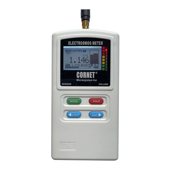
The ED85EXP5 has four push buttons: "MODE", "HOLD", "LIGHT", and "UNIT".
"MODE" button is used to switch in between RF mode, and
two LF modes.
"HOLD" button is used to halt the data measurement. Push the
button again to exit the "Hold" condition. a "HOLD" Mark is
shown on the LCD screen to indicate the "Hold" condition.
"UNIT" button select the mw/m2,v/m,or dBm unit.
"LIGHT" button turn on/off the LCD backlight and Audio sound
(5)
RF mode:
The digital LCD display shows the measured RF field strength or power (in dBm, v/m, or
mw/m2). For quick RF signal level indications, 8 LED lights in red, yellow, and green are used. Three
red LEDs are used to represent the three countries' safety ranges. The signal power level of each LED
can be found in the table on the back panel of the ED85EXP5.
The frequency of the detected signal is also recorded. displayed in real time on the LCD display
©2022 CORNET Microsystem Inc., 1400 Coleman Ave #C28 Santa Clara, CA 95050 USA
www.cornetmicro.com
ED85EXPlus5 V.1.1 09/12/2022
v.1.1 9/12/2022
(ED85EXP5)Electrosmog Meter measures high
Please download new version of manual
from: www.cornetmicro.com
(6)
LF mode:
The digital LCD display shows the measured LF magnetic field strength (in uT and
mGauss). Using the "MODE" button, you can choose between two LF modes:
(a)
LF30 mode: has a high sensitivity (0.1mG-10mG) but a narrower frequency range (50Hz-1kHz) to
reduce high-frequency noise. (The Histogram and LED segment display can still show up to
30mG.)
(b)
LF600 mode: has a sensitivity (1mG-600mG), covers a wider frequency range (50Hz -10kHz).
* The magnetic field level can also be displayed using 8 different colored LED lights.
* Due to the LF30 mode's reduced frequency coverage range, the LF30 mode may show lower readings than
the LF600 mode for monitoring high frequency digital/pulse signals (such as switching power supplies),
(6)
Histogram:
For RF, and LF modes, the previous 30 signal level values are recorded and
shown as a moving graph on the LCD display. It can be used to locate the source of a
signal and to record digital RF burst bursts such as transmissions from AC Smart meter.
(7)
MAX:
The LCD display displays the maximum measured data value since the last power-on.
(8)
Average:
The "A" or "P" mark on the LCD indicates whether the result is Whole-average or
Peak-average. The Peak-average is the average of the 30 data in the histogram, and the
Whole-Average is the total of all sampled data divided by the number of data within the
screen update period.
(9) Sound function & LCD backlight:
Toggling the "LIGHT" button turns on/off the LCD backlight
and the Audio Sound function (a "S" symbol on the LCD indicates the sound mode is on).
The sound level can be adjusted using the wheel volume control. Audio Sound may be used
to detect type of RF signals, or for the detection of low level radio frequency (RF) signals.
(down to 0.05uw/m2). When not in use, turn off the LCD backlight or the sound to save
battery power.
SysSetup Menu:
(10)
To access the SysSetup menu, press and hold the "UNIT" button, then click the
"HOLD" button. To move the cursor in the Menu, use the ">" button, and to enable/disable
the functionalities, use the "<" button. From the SysSetup menu, select:
(a) EXIT:
exiting the SysSetup menu and back to Normal operating mode.
(b) RF level Unit select: select mw/m2, v/m, or dBm as the default Unit when meter is powered on.
(c) LED Level: used to adjust customized color LED segment display level for certain safety
standards. OFF, -5,-10,-15,-20dB, or LED NO Display are the options.
(For "SBM2015 Building Biology Testing Methods," use -20dB)
(d) Average/Frequency: select Peak average, whole Average, or Frequency of MAX value.
(e) MAX_Clear bit: If it is "ON" the MAX value can be cleared by toggling the "HOLD" button. If it is
"OFF" the MAX value can be cleared only by power-off the meter.
(f) Alarm:
ON/OFF or one of the 8 trigger levels (0, -5,-10,-15,-20,-25,-30,-35dBm) can
be selected to trigger the audio Alarm. *(Alarm function is for RF mode only).
2,
(g) RESET:
Reset to default (mw/m
LED Level OFF, MAX_CLEAR ON, Alarm OFF, PeakAvg).
(h) SAVE:
To save the changes to EEPROM memory, press the "<" button, wait until it is
"done!" before turning off the meter. (If you exit without first saving the changes
to memory, the changes will still work, but they will be lost if the meter is turned off.)
(11) While in LF mode (magnetic measurement), hold the meter steady to get a good stable reading,
avoid fast moving the meter to avoid sudden changes in the reading which is caused by the Earth
magnetic field or induced electric fields from nearby objects.
(12) AC Smart meters emit RF signals in short bursts every few minutes, which can be captured and
viewed on the LCD screen using the Histogram or Data Logging function of the ED85EXP5.
(13) Data Logging menu:
To access the Logger Setup menu, press and hold the "UNIT" button, then
click the "MODE" button. Please see the "ED85EXP5 Data Logging user Guide" available at
www.cornetmicro.com for instructions on how to transfer Data Logging data to a PC computer via a Micro-
USB serial interface cable.
Advertisement
Table of Contents

Related Manuals for CORNET ED-85EXPlus5


Summary of Contents for CORNET ED-85EXPlus5
- Page 1 "MODE" button. Please see the "ED85EXP5 Data Logging user Guide" available at www.cornetmicro.com for instructions on how to transfer Data Logging data to a PC computer via a Micro- USB serial interface cable. ©2022 CORNET Microsystem Inc., 1400 Coleman Ave #C28 Santa Clara, CA 95050 USA www.cornetmicro.com ED85EXPlus5 V.1.1 09/12/2022...
- Page 2 #1023 on the left hand side of the cursor) view mode. While in the Data Logging view mode, Push the "HOLD" button will enter the Temp HOLD mode. ©2022 CORNET Microsystem Inc., 1400 Coleman Ave #C28 Santa Clara, CA 95050 USA www.cornetmicro.com ED85EXPlus5 V.1.1 09/12/2022...
- Page 3 The Duty Cycle of the continue wave analog AM/FM signal will be close to 100%. (b) RF level Unit select (c) LED Level (d) Average/Frequency SysSetup menu (e) MAX_Clear (f) Alarm (g) RESET (h) SAVE LoggerSetup menu ©2022 CORNET Microsystem Inc., 1400 Coleman Ave #C28 Santa Clara, CA 95050 USA www.cornetmicro.com ED85EXPlus5 V.1.1 09/12/2022...
- Page 4 Maximum RF input power to SMA connector of the meter is +10dBm, use RF attenuator in front of the SMA input connector to protect the RF sensor inside the meter from burn out. ©2022 CORNET Microsystem Inc., 1400 Coleman Ave #C28 Santa Clara, CA 95050 USA www.cornetmicro.com...
- Page 5 Extreme Concern Concern Concern Concern <0.3 0.3-1.5 1.5-10 >10 Electric <0.2 0.2-1 >5 Magnetic <0.02 0.02-0.1 0.1-0.5 >0.5 mw/m² <0.0001 0.0001-0.01 0.01-1 >1 ©2022 CORNET Microsystem Inc., 1400 Coleman Ave #C28 Santa Clara, CA 95050 USA www.cornetmicro.com ED85EXPlus5 V.1.1 09/12/2022...
Need help?
Do you have a question about the ED-85EXPlus5 and is the answer not in the manual?
Questions and answers