Table of Contents
Advertisement
Quick Links
Advertisement
Table of Contents

Related Manuals for ETS 871


Summary of Contents for ETS 871
- Page 1 WIDE RANGE RESISTANCE METER Model 871 Operating Instructions 10/10...
-
Page 2: Important Safety Instructions
IMPORTANT SAFETY INSTRUCTIONS (Equipment without HV) The equipment described in this Manual is designed and manufactured to operate within defined design limits. Any misuse may result in electric shock or fire. To prevent the equipment from being damaged, the following rules should be observed for installation, use and maintenance. -
Page 3: Maintenance And Service
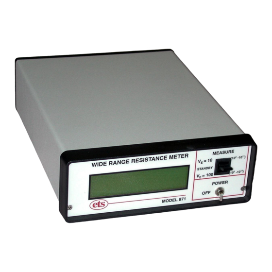
DO NOT OPERATE IN HIGH HUMIDITY: Operating the equipment in high humidity conditions will cause deteriation in performance, system failure, or present a shock or fire hazard. Contact the factory for further instructions. DO NOT OPERATE IN AREAS WITH HEAVY DUST: Operating the equipment in high dust conditions will cause deteriation in performance, system failure, or present a shock or fire hazard. - Page 4 Figure 1.0-1: Model 871 2.0 DESCRIPTION The Model 871 Wide Range Resistance Meter is an accurate, easy to use laboratory grade, microprocessor-based, autoranging instrument. The Meter is activated when the MEASURE select paddle switch is placed in either the V =10V or 100V position.
- Page 5 Generally, probes with 36” (1m) cables will require an electrification time of approximately 60 seconds to achieve maximum reading. External probes are connected to the Model 871 via standard banana jacks located on the rear of the instrument. Refer to available ETS Series 800 Resistance/Resistivity Probes literature sheets for probes to meet virtually any surface, volume (solids, liquids and powders) and point-to-point resistance measurement requirement.
- Page 6 3.0 OPERATION Hook-up Connect the probe to the input banana jacks located on the rear panel as shown in Figures 3.1-1 to 3.1-5 for measuring surface, point-point and point to ground (RTG) resistance. The Red jack is V (test voltage), the Black Jack is SENSE (measuring input) and the Green jack is probe ground.
- Page 7 Figure 3.1-3: Connection for measuring 2-point resistance per ESDA STM 11.13 Figure 3.1-4: Connection for measuring point-to-point resistance and RTG per ESDA STM 4.1 D01904 Rev A...
- Page 8 When applicable, the resistance measurement can be converted to resistivity by multiplying the measured resistance by the appropriate probe configurations. For the ETS Model 803B Surface/Volume Resistance Probe multiply the measured surface resistance by 10 (...
-
Page 9: Measurement Considerations
To measure pt-to-pt resistance or RTG plug an ETS Model 850, 845 or equivalent probe into the V (Red) jack. To measure pt-pt, place the probes onto the surface to be measured. To measure RTG connect the supplied red wire... - Page 10 Another area that should be considered when attempting to measure surface resistance is the composition of the material being evaluated. ANSI/ASTM D- 257, a widely used test standard, is specified for homogeneous, insulating material. However, many materials are either not homogeneous, relatively conductive and in the case of some composite material, nonlinear.
- Page 11 voltage is applied to establish continuity the resistance path created may become altered permanently. It should be noted that loaded thermoplastic materials are only effective in reducing the upper resistance limit to approximately 10 Ohms. Another characteristic of loaded thermoplastic materials that affects the resistance measurement is the microscopic insulative layer that develops on the surface of the molded part.
- Page 12 However, this specification is for insulating materials and when the bulk characteristics of the material come into play significant errors are introduced. This became apparent during packaging material specification development approximately 15 years ago. It was found that by specifying all test parameters measurement variations between laboratories testing the same material was reduced from 3 orders of magnitude to better than one-half order of magnitude.
-
Page 13: Computer Interface
5.0 COMPUTER INTERFACE The Model 871 has a 9-Pin sub min-D RS232A COMM PORT (Note 1) that provides real time data through serial communication. A PC will receive data by simply sending character R (for result) to the device. -
Page 14: Maintenance
STANDBY, OVERSCALE or UNDERSCALE (Note 2), the unit will send the same message. However, the actual result will be sent without any decimal point. For example, if the LCD displays 5.00 e+6 Ω, the ETS 871 will send 500 e+4 to the host computer instead. - Page 15 Figure 6.0-1: Changing batteries 10/10 D01904 Rev A...
-
Page 16: Warranty
7.0 WARRANTY Limited Warranties. Seller warrants that all goods manufactured and delivered hereunder shall (a) conform to any samples, drawings, specifications or other written documents provided to Seller by Buyer, or approved by Buyer to Seller and (b) be free from all defects in workmanship and material.
Need help?
Do you have a question about the 871 and is the answer not in the manual?
Questions and answers