Advertisement
Quick Links
InStallatIon anD maIntenanCe InStruCtIonS
rtS151
remote test Station
SpeCIfICatIonS
Dimensions:
Weight:
Power Requirements
Alarm LED:
Coil Current:
Test Switch:
Reset Switch:
Alarm Response Time:
Temperature:
Humidity:
NOTE: RTS151 replaces RTS451.
NOTICE: This manual shall be left with the owner/user of this equipment.
NOTE: A test coil is required only for use with D2/DNR/DH400/DH500 mod-
els. For D2 models order part #DCoil. For the DH400/500 models order part
is #Coil.
General InformatIon
System Sensor's RTS151 is an automatic fire detector accessory designed to
test a remotely located detector. Consult detector installation instructions for
additional information.
The National Fire Protection Association has published codes, standards, and
recommended practices for the installation and use of the above product. It is
recommended that the installer be familiar with these requirements, with local
codes, and any special requirements of the local authority having jurisdiction.
rtS151 ContentS
1 RTS151 remote test station
1 screw pack (2 mounting screws)
1 M02-04 test magnet
WIrInG of rtS151
Consult the appropriate detector installation instructions for the applicable
wiring diagram. The RTS151 mounts to a single gang box (2
depth), or directly to the wall or ceiling.
See Figure 8 for wiring diagram of RTS151 with Duct Smoke Detectors.
In Canadian applications, the RTS151 is intended to be located in the same
room as the smoke detector and within 60 feet of the unit.
operatIon
Test Function
Place and hold the painted side of the magnet to the test location RTS151.
Alarm Indication
With the magnet in place some time will elapse (40 sec. maximum) depend-
ing on the detector type, before the alarm indicating LED will light.
Reset Function
1
Gently insert a
/
˝ maximum diameter tool into the hole until it stops and
8
LED turns off. The RTS151 is capable of resetting only certain System Sensor
models of detectors. Refer to detector installation instructions for additional
information.
D440-01-00
4.8˝ H × 2.90˝ W × 1.4˝ D
.16 lbs.
2.8 – 32 VDC, 10 mA max.
95 mA max.
10 VA @ 32 VDC
10 VA @ 32 VDC
40 sec. max.
–10°C to 60°C (14°F to 140°F)
95% RH Non-condensing Max
1
/
" minimum
2
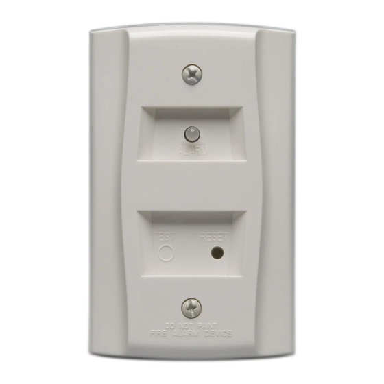
fIGure 1. rtS151 remote teSt StatIon:
fIGure 2. WIrInG DIaGram for rtS151 to D4120 4-WIre DuCt
Smoke DeteCtor:
RTS151
FIELD
2
INSTALLED
4
JUMPER
1
(RED LED)
ALARM
5
3
fIGure 3. WIrInG DIaGram for rtS151 to D2-2WIre DuCt
Smoke DeteCtor:
TEST COIL +
TEST COIL –
COMM +
OUT (CONV ONLY) +
COMM –
RA/RTS –
RA +
RTS +
NOTE: THE RTS151 TEST COIL CIRCUIT
REQUIRES AN EXTERNAL 24 VDC POWER
SUPPLY WHICH MUST BE UL LISTED.
NOTE: THE USE OF A REMOTE TEST STATION REQUIRES THE
INSTALLATION OF AN ACCESSORY COIL, PART NUMBER DCOIL,
SOLD SEPARATELY.
1
3825 Ohio Avenue, St. Charles, Illinois 60174
1-800-SENSOR2, FAX: 630-377-6495
www.systemsensor.com
TEST RESET
D4120
AUX OUT +
AUX OUT –
ALARM
R TEST
R RESET
4
5
*
EXTERNAL
(-) POWER (+)
SUPPLY
1
2
3
RTS151
REMOTE TEST STATION
LED OPTION
1 PER UNIT
10mA CURRENT DRAW
TEST COIL OPTION
1 PER UNIT
95mA CURRENT DRAW
H0196-01
H0582-11
H0571-08
I56-0469-011
Advertisement

Related Manuals for System Sensor RTS151


Summary of Contents for System Sensor RTS151
- Page 1 60 feet of the unit. R RESET operatIon Test Function Place and hold the painted side of the magnet to the test location RTS151. Alarm Indication H0582-11 With the magnet in place some time will elapse (40 sec. maximum) depend- fIGure 3.
- Page 2 H0586-03 three-Year limited Warranty System Sensor warrants its enclosed product to be free from defects in materials and #__________, 3825 Ohio Avenue, St. Charles, IL 60174. Please include a note describing workmanship under normal use and service for a period of three years from date of the malfunction and suspected cause of failure.
Need help?
Do you have a question about the RTS151 and is the answer not in the manual?
Questions and answers