
Related Manuals for W.E.S.T. Elektronik POS-123-P-PFN

Summary of Contents for W.E.S.T. Elektronik POS-123-P-PFN
- Page 1 Technical Documentation POS-123-P-PFN Universal position control module with integrated power stage and Profinet interface...
-
Page 2: Table Of Contents
VMAX (Maximum speed in NC mode) ....................25 5.4.5 (Loop gain setting) ........................... 26 5.4.6 V0:RES (Resolution of the Loop Gain Input) ..................26 5.4.7 A (Acceleration time)..........................27 5.4.8 D (Deceleration / braking distance) ....................... 27 Page 2 of 53 POS-123-P-PFN 31.03.2021... - Page 3 Parameterisation via Profinet ........................47 7.7.1 Procedure ............................47 7.7.2 Parameter List ............................48 Profinet-Driver Blocks for Simatic-Controllers ....................... 49 Integration of the Block into the PLC program ....................49 Function ................................ 52 Notes ..................................53 Page 3 of 53 POS-123-P-PFN 31.03.2021...
-
Page 4: General Information
1 General Information 1.1 Product Name POS-123-P-PFN-2040 positioning control module with analog sensor interface, integrated power stage and Profinet interface Alternative products: POS-123-P standard device with analog command signals 1.2 Scope of supply The scope of supply includes the module plus the terminal blocks which are part of the housing. -
Page 5: Symbols Used
We reserve the right to make technical modifications due to further development of the product described in this manual. The technical information and dimensions are non-binding. No claims may be made based on them. This document is protected by copyright. Page 5 of 53 POS-123-P-PFN 31.03.2021... -
Page 6: Safety Instructions
• The module may not be used in an explosive environment. • To ensure adequate cooling the ventilation slots must not be covered. • The device must be disposed of in accordance with national statutory provisions. Page 6 of 53 POS-123-P-PFN 31.03.2021... -
Page 7: Characteristics
Application oriented parameterising • Controlling and monitoring via fieldbus • Integrated power stage • Individual profile demand by speed, acceleration and delay • Fault diagnosis and extended function checking • Simplified parameterisation with WPC-300 software Page 7 of 53 POS-123-P-PFN 31.03.2021... -
Page 8: Device Description
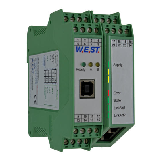
Klemmblöcke (steckbar) 22 23 24 Terminals (removable) W.E.ST. LEDs Ready A Supply Error Interface Feldbus / Fieldbus State Profinet LEDs LinkAct1 LinkAct2 Feldbus / Fieldbus 9 10 11 12 RJ45 Profinet 14 15 16 Page 8 of 53 POS-123-P-PFN 31.03.2021... -
Page 9: Use And Application
Switched inductances (relays and valve coils) which are connected to the same power supply must always be provided with appropriate overvoltage protection directly at the coil. Page 9 of 53 POS-123-P-PFN 31.03.2021... -
Page 10: Method Of Operation
When the HAND (+ or -) signal is switched off, the current actual position is accepted as the required position and the drive comes to a controlled stop. The HAND mode can be used-in case of a sensor failure-to drive the axis manually. Page 10 of 53 POS-123-P-PFN 31.03.2021... - Page 11 Page 11 of 53 POS-123-P-PFN 31.03.2021...
-
Page 12: Influences On Positioning Accuracy
The following illustrations show two possible speed profiles, which result depending on the choice of speed V2 in relation to V1: High to low speed acceleration deceleration time / position Low to high speed time / position acceleration deceleration Page 12 of 53 POS-123-P-PFN 31.03.2021... -
Page 13: Commissioning
START If START is disabled, the axis stops in the preset deceleration distance D:S. Controller optimization Now optimize the control parameters according to your application and its requirements. Page 13 of 53 POS-123-P-PFN 31.03.2021... -
Page 14: Technical Description
Both yellow LEDs flash oppositely every 1 s: The nonvolatile stored parameters are in- YELLOW B consistent! To acknowledge the error, data has to be saved with the SAVE command or the corresponding button in the WPC. Page 14 of 53 POS-123-P-PFN 31.03.2021... -
Page 15: Second Section (Right Part Of Module)
Working network connected to port 1. FLICKERING: Data traffic with network at port 1. GREEN LinkAct2: OFF: No connection at port 2. ON (Pulse): Working network connected to port 2. FLICKERING: Data traffic with network at port 2. Page 15 of 53 POS-123-P-PFN 31.03.2021... -
Page 16: Circuit Diagram
4.3 Circuit diagram POS-123-P-PFN Power supply common Supply fieldbus and power stage Speed demand via Profinet to solenoid A Command Power Profile Position Valve position Generator controller via Profinet stage adaption to solenoid B Position Input feedback scaling ENABLE READY... -
Page 17: Typical Wiring
Sensor 4... 20 mA two wire connection +In PIN 14 +In PIN 14 In PIN 11 (GND) PIN 11 (GND) e.g. 24 V Sensor 4... 20 mA three wire connection +In PIN 14 PIN 11 (GND) Page 17 of 53 POS-123-P-PFN 31.03.2021... -
Page 18: Technical Data
-20… 70 Storage temperature [°C] Humidity < 95 (non-condensing) Connections Communication USB type B Plug connectors 4 x 4-pole terminal blocks via the DIN mounting rail EN 61000-6-2: 8/2005 EN 61000-6-4: 6/2007 + A1:2011 Page 18 of 53 POS-123-P-PFN 31.03.2021... -
Page 19: Parameter
Closed loop gain in NC mode V0:B V0:RES Switchover of the resolution. Control parameter SDD Acceleration (ramp times) in SDD mode Deceleration stroke in SDD mode Common PT1 time constant CTRL SQRT1 Control characteristics Page 19 of 53 POS-123-P-PFN 31.03.2021... - Page 20 Current loop auto adjustment PPWM Closed loop current controller IPWM 2600 Maximum current limitation Special commands Ainmode AINMODE EASY Input scaling mode AIN:I I= X Free scaling of the analogue inputs (MATH) 1000 1000 0.01 % Page 20 of 53 POS-123-P-PFN 31.03.2021...
-
Page 21: System Parameters
Auto reset mode. All monitoring functions are active. If the failure doesn’t exist anymore, the AUTO: module automatically resumes to work. Normally the monitoring functions are always active because otherwise no errors are detectable via the READY output. Deactivating is possible mainly for troubleshooting. Page 21 of 53 POS-123-P-PFN 31.03.2021... -
Page 22: Passfb (Password For Fieldbus)
The manual speed is also limited by the (internal or external) speed demand (MIN evaluation). Caution! Do not use the manual mode in conjunction with the EOUT command. After the deactivation of the HAND input the output is set to the EOUT value. Page 22 of 53 POS-123-P-PFN 31.03.2021... -
Page 23: Poswin:s (Static Position Monitoring)
I4-20 U10-0 I20-4 This command is used to define the type of the input signal (voltage or current) and to set the direction of the signal. This is available for the analogue sensor input. Page 23 of 53 POS-123-P-PFN 31.03.2021... -
Page 24: N_Range:x (Sensor Nominal Pressure)
5.4 Position Controller 5.4.1 VRAMP (Ramp time for external speed demand) Command Parameters Unit Group VRAMP x= 10… 5000 CONTROL The rate of change of the external speed demand can be limited by this ramp time. Page 24 of 53 POS-123-P-PFN 31.03.2021... -
Page 25: Vmode (Methode Of Positioning)
(not too high under any circumstances). The speed is scaled by means of the external speed demand. The command is only active if the VMODE has been parameterized to NC. If the speed of the drive differs between retraction and extension, the lower speed must be set. Page 25 of 53 POS-123-P-PFN 31.03.2021... -
Page 26: Loop Gain Setting)
This switchover to 100 should only be carried out for very small values (V0 < 4), as the input range is limited to 400. The loop gain is alternatively defined as a KV factor with the unit (m/min)/mm or as V in 1/s. The conversion is KV = V /16,67. Page 26 of 53 POS-123-P-PFN 31.03.2021... -
Page 27: A (Acceleration Time)
Parameter D:S is used as the stopping ramp when disabling the START signal. After disabling, a new target position (current position plus D:S) is calculated in relation to the speed and is specified as a command value. RANGE Calculation of control gain Intern Page 27 of 53 POS-123-P-PFN 31.03.2021... -
Page 28: Pt1 (Time Constant Of The Controller)
This setting should only be used with a significantly progressive flow through the valve. The SQRT function generates constant deceleration and thus reaches the target position faster. This is achieved by increasing the gain during the deceleration process. Page 28 of 53 POS-123-P-PFN 31.03.2021... -
Page 29: Output Signal Adaptation
This can lead to vibrations and jittery behavior. To compensate this, the TRIGGER value should be set to approximately 200 and the MIN value to 100. The gain in the zero point is thus halved and an over- all higher gain can often be set. Page 29 of 53 POS-123-P-PFN 31.03.2021... -
Page 30: Offset (Zero Correction)
This command is used to switch the polarity of the control signal. 5.6 Power stage 5.6.1 CURRENT (Rated output current) Command Parameters Unit Group CURRENT x= 500… 2600 POWERSTAGE The nominal output current is set. Dither and also MIN/MAX always refer to this current range. Page 30 of 53 POS-123-P-PFN 31.03.2021... -
Page 31: Dampl (Dither Amplitude)
The dither amplitude is a command signal. Derivations between the commanded amplitude and the real amplitude are possible, depending on the dynamic of the solenoid. The lower the dither frequency, the smaller the steps. Therefore no practical problems are expected. Page 31 of 53 POS-123-P-PFN 31.03.2021... -
Page 32: Acc (Current Loop Auto Adjustment)
Typical values are: PPWM = 1... 3 and IPWM = 40... 80. If the PWM frequency is > 1000 Hz, the default values of PPWM = 7 and IPWM = 40 should be selected. Page 32 of 53 POS-123-P-PFN 31.03.2021... -
Page 33: Ims (Theoretical Maximum Current Drain)
The MATH mode supports the free input scaling by a linear equation. This mode is compatible to our older modules. Attention: This command can be executed in the terminal window only. In case of switching back, DEFAULT data should be reloaded. Page 33 of 53 POS-123-P-PFN 31.03.2021... -
Page 34: Ain (Analogue Input Scaling)
1250 1000 2000 C signal (16 mA = 20 mA-4 mA) will be gained to 100 % (20 mA). Each of this parameterisation for 4… 20 mA is setting the range to 0… 100 %. Page 34 of 53 POS-123-P-PFN 31.03.2021... -
Page 35: St (Status Report)
Output of the controller Control Signal Solenoid current A Solenoid current B VACT Measured Speed mm/s The process data are the variables which can be observed continuously on the monitor or on the oscilloscope. Page 35 of 53 POS-123-P-PFN 31.03.2021... -
Page 36: Appendix
The RC in monitor mode can be used to analyze faults. CAUTION: All safety aspects must be thoroughly checked when working with the RC (Remote Control) mode. In this mode the module is controlled directly and the machine control cannot influence the module. Page 36 of 53 POS-123-P-PFN 31.03.2021... - Page 37 The drive moves in and out too fast leading to uncontrolled behavior. Reducing the speed demand has very little or no effect. The hydraulic system is over-sized. The entire parameterisation of the movement cycle cannot be reproduced (overlap and deceleration distance settings) Page 37 of 53 POS-123-P-PFN 31.03.2021...
-
Page 38: Profinet Io Rt Interface
In the configuration of transmission, 32 bytes for input and 32 bytes for output must be pre-adjusted. Page 38 of 53 POS-123-P-PFN 31.03.2021... -
Page 39: Io Description
Nominal/limit speed for movement in the second profile segment (Entering this value activates the second profile segment) PARAMETER ADDRESS Address of the parameter which should be changed or read out PARAMETER VALUE Value of the parameter to be transmitted Page 39 of 53 POS-123-P-PFN 31.03.2021... - Page 40 Control signal to the power stage (U) SPEED The current speed of the axis (VACT) SOLENOID CURRENT A Current at solenoid A (IA) SOLENOID CURRENT B Current at solenoid B (IB) PARAMETER VALUE Parameter value, requested by PARA READ Page 40 of 53 POS-123-P-PFN 31.03.2021...
-
Page 41: Commands Via Profinet
UINT16 100 % = 0x3FFF Speed demand 2 Low Parameter value High (MSB) Depending on Depending on long selected selected parameter parameter Parameter value Low (LSB) Parameter address High 0… 0x2200 Parameter address Low Page 41 of 53 POS-123-P-PFN 31.03.2021... -
Page 42: Definition Control Word 1
Byte 0-control word High Function DIRECT Directly processing of new position demands HAND:B Manual movement HAND:A Manual movement START Activation of the positioning process ENABLE General enabling of the system Byte 1-control word Low Function Page 42 of 53 POS-123-P-PFN 31.03.2021... -
Page 43: Definition Control Word 2
PARAREAD returns the lower limit for the selected parameter READULIM PARAREAD returns the upper limit for the selected parameter PARA READ Reading out the selected address PARA VALID Transmitting parameterisation PARA MODE Activation of the parameterising mode Page 43 of 53 POS-123-P-PFN 31.03.2021... -
Page 44: Feedback Via Profinet
0… 2600 UINT16 Solenoid current B Low Measured Speed High INT16 +/- 30000 0.1 mm/s Measured Speed Low Parameter value High (MSB) Depending Depending on selected on selected long parameter parameter Parameter value Low (LSB) Page 44 of 53 POS-123-P-PFN 31.03.2021... -
Page 45: Definition Status Word 1
SEGMENT 2 Second profile segment is active POSWIN:S Target position within the monitoring window POSWIN:D Following distance within the monitoring window READY System is enabled and no errors were detected Byte 1-status word Low Function Page 45 of 53 POS-123-P-PFN 31.03.2021... -
Page 46: Definition Status Word 2
X ERROR Field bus communication error BUS ERROR Internal data error DERROR Byte 3-status word Low Function LIVEBIT OUT Monitoring of the communication PARA READY Parameterisation successfully transmitted PARA ACTIVE Parameterisation via fieldbus is active Page 46 of 53 POS-123-P-PFN 31.03.2021... -
Page 47: Parameterisation Via Profinet
PARA ACTIVE bit). Only restarting the device enables three new attempts. Please note that a storage of the parameterisation via Profinet is limited in the number of writing cy- cles. This means it should be done only when necessary. Page 47 of 53 POS-123-P-PFN 31.03.2021... -
Page 48: Parameter List
0x2054 PWM frequency, preset in steps according to table in 5.6.4,. 1 = 60 Hz, ..,, 20 = 2941 Hz 0x2055 Maximum current limit 0x2100 SAVE Saving the data set 0x2200 Password for parameterisation Page 48 of 53 POS-123-P-PFN 31.03.2021... -
Page 49: Profinet-Driver Blocks For Simatic-Controllers
“System constants”: If a controller of the S7-300 and -400 series is used, the input and output addresses of the I/O-Module are the required information for the driver block, see over. Page 49 of 53 POS-123-P-PFN 31.03.2021... - Page 50 2.) The driver block is supplied as SCL-source. In order to assemble it into the project, the file has to be added to the TIA-Portal as “new external file”: Page 50 of 53 POS-123-P-PFN 31.03.2021...
- Page 51 This FB can now be called out of the application program. This should happen in a cyclic interrupt with an execution time >= 8 ms. View of the block in FUP without interconnection: Address designation for S7-300 / -400 (example): Page 51 of 53 POS-123-P-PFN 31.03.2021...
-
Page 52: Function
If the output values are processed and used to control further functions, the valid bit has also to be con- sidered. In case of a bus failure adequate fall-back values have to be used so that the complete system in kept in a safe state. Page 52 of 53 POS-123-P-PFN 31.03.2021... -
Page 53: Notes
9 Notes Page 53 of 53 POS-123-P-PFN 31.03.2021...
Need help?
Do you have a question about the POS-123-P-PFN and is the answer not in the manual?
Questions and answers