
Related Manuals for W.E.S.T. Elektronik POS-124-A-PDP

Summary of Contents for W.E.S.T. Elektronik POS-124-A-PDP
- Page 1 W.E.ST. Elektronik GmbH Technical Documentation POS-124-A-PDP POS-124-I-PDP Two axes positioning and synchronisation control module with integrated profibus interface and SSI sensor interface...
-
Page 2: Table Of Contents
W.E.ST. Elektronik GmbH CONTENTS General Information ............................. 4 Order number .............................. 4 Scope of supply ............................4 Accessories ..............................4 Symbols used .............................. 5 Using this documentation ..........................5 Legal notice ..............................5 Safety instructions ............................6 Characteristics ..............................7 Device description ............................ - Page 3 W.E.ST. Elektronik GmbH 5.2.26 HAND1 / HAND2 (Manual speed) ..................... 31 5.2.27 MIN / MIN2 (Overlap compensation) ....................32 5.2.28 MAX1 / MAX2 (Limitation) ......................... 32 5.2.29 TRIGGER (Response threshold for the MIN parameter) ..............32 5.2.30 OFFSET1 / OFFSET2 (Zero correction) .................... 33 5.2.31 INPOS:S1 / INPOS:S2 (In position window) ..................
-
Page 4: General Information
W.E.ST. Elektronik GmbH 1 General Information 1.1 Order number POS-124-A-PDP-1121 triple stage module with digital SSI-interface with analogue ±10 V differential output, housing width 67,5 mm POS-124-I-PDP-1121 triple stage module with digital SSI-interface with analogue 4… 20 mA output, housing width 67,5 mm... -
Page 5: Symbols Used
W.E.ST. Elektronik GmbH 1.4 Symbols used General information Safety-related information 1.5 Using this documentation Structure of the documentation: The standard product is descibed up to chapter 6. The extensions like POWER STAGE or SSI-INTERFACE are described in the chapters ADDITIONAL INFORMATION. 1.6 Legal notice W.E.St. -
Page 6: Safety Instructions
W.E.ST. Elektronik GmbH 1.7 Safety instructions Please read this document and the safety instructions carefully. This document will help to define the product area of application and to put it into operation. Additional documents (WPC-300 for the start-up software) and knowledge of the application should be taken into account or be available. General regulations and laws (depending on the country: e.g. -
Page 7: Characteristics
W.E.ST. Elektronik GmbH 2 Characteristics This electronic module has been developed for controlling hydraulic positioning drives. Both axes are controlled complete autonomous via the Profibus. Optionally an interconnection to a two axes synchronised system is intended. The differential outputs are covered for activation of constant valves with integrated or external electronics (differential input). -
Page 8: Device Description
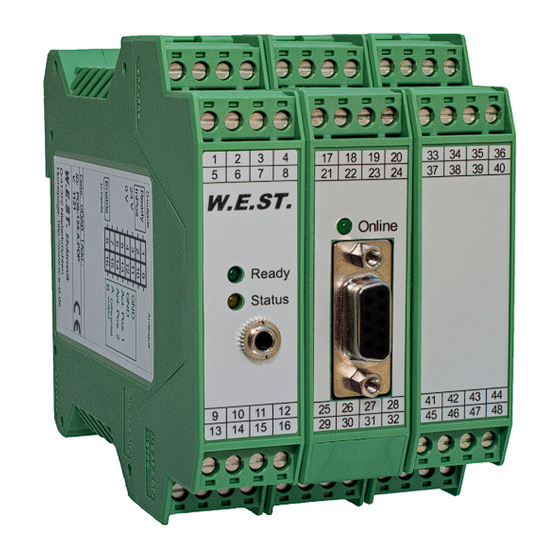
W.E.ST. Elektronik GmbH 2.1 Device description 99,0000 mm 67,5000 mm D-outputs Analogue Ready 24 V Pos. 1 121,0000 mm Pos. 2 114,0000 mm Differential output Enable D-inputs Made in Germany Date: Add.: W.E.ST. Elektronik D-41372 Niederkrüchten Homepage: http://www.w-e-st.de 18 19 20 34 35 36 Typenschild und Anschlussbelegung Type plate and terminal pin assignment... -
Page 9: Use And Application
W.E.ST. Elektronik GmbH 3 Use and application 3.1 Installation instructions This module is designed for installation in a shielded EMC housing (control cabinet). All cables • which lead outside must be screened; complete screening is required. It is also a requirement that no strong electro-magnetic interference sources are installed nearby when using our control and regulation modules. -
Page 10: Typical System Structure
W.E.ST. Elektronik GmbH 3.2 Typical system structure This minimal system consists of the following components: (*1) proportional valve (*2) hydraulic cylinder (*3) position sensor (*4) POS-124-PDP control module (*5) interface to PLC with analogue and digital signals 3.3 Method of operation This control module supports simple point-to-point positioning with hydraulic drives. - Page 11 W.E.ST. Elektronik GmbH Positioning sequence: The positioning is controlled via Profibus. After releasing (ENABLE input), the command position is set to the actual position of the sensor and the axis stays in closed loop position control mode. The READY output indicates that the system is generally ready for operation. When setting the START-signal, the preset command value will be taken over.
-
Page 12: Commissioning
W.E.ST. Elektronik GmbH 3.4 Commissioning Step Task Installation Install the device in accordance with the circuit diagram. Ensure it is wired correct- ly and that the signals are well shielded. The device must be installed in a metal protective housing (control cabinet or similar). Switching on for the first Ensure that no unwanted movement is possible in the drive (e.g. -
Page 13: Technical Description
W.E.ST. Elektronik GmbH 4 Technical description 4.1 Input and output signals Connection Supply PIN 3, PIN 31 Power supply (see technical data) and PIN 35 PIN 4, PIN 32 0 V (GND) connection. and PIN 36 Caution, PIN 4 is connected internally to PIN 11 (and also possibly to PIN 12 depending on the model). -
Page 14: Led Definitions
W.E.ST. Elektronik GmbH 4.2 LED definitions LEDs Description of the LED function GREEN Identical to the READY output. OFF: no power supply or ENABLE is not activated System is ready for operation Flashing: Error discovered (valve solenoid or 4… 20 mA). The error of one axis results to a flashing LED. -
Page 15: Circuit Diagram
W.E.ST. Elektronik GmbH 4.3 Circuit diagram POS-124-A/I-PDP Profibus SUBD Profibus DP 9polig 24 V Internal Power 24 V PELV VMODE = SDD Speed via Feldbus VMODE = NC Differentialinput Output Adaptation Control Function Output: A Profil Generator Commands: Commands: Commands: - MIN: A and B Position - A:A and A:B... -
Page 16: Typical Cabling
W.E.ST. Elektronik GmbH 4.4 Typical cabling power supply +/- 10 V (4...20mA) to control valve 2 +24 V DC SSI 1 sensor interface CLK+ ENABLE CLK- DATA+ DATA- DATA- DATA+ CLK- CLK+ SSI 2 sensor interface 0..10V, 4..20mA +24 V DC sensor position 13 = X1, 14 = X2 +/- 10 V (4...20mA) -
Page 17: Technical Data
W.E.ST. Elektronik GmbH 4.6 Technical data Supply voltage [VDC] 24 (±10 %) Current requirement [mA] External protection 1 medium time lag Digital inputs logic 0: < 2 V logic 1: > 10 V,current consumption < 0,1 mA [kOhm] Input resistance Digital outputs logic 0: <... -
Page 18: Parameters
W.E.ST. Elektronik GmbH 5 Parameters 5.1 Parameter overview Command Default Unit Description Changing language help texts. PDPADR Address of the unit at the Profibus. MODE Mode parameter. SENS Activation and disabling of internal failure monitor- ing functions. INPX Switching between SSI and analog sensors. STROKE1 X = 10...10000 Working stroke of the sensor. - Page 19 W.E.ST. Elektronik GmbH MIN1:I 0,01 % Zero point setting /following error compensation. MIN2:I 0,01 % MAX1:I 10000 0,01 % Maximum output signal limitation. MAX2:I 10000 0,01 %% TRIGGER1 0,01 % Trigger threshold for activating the following error TRIGGER2 0,01 %% compensation (MIN).
-
Page 20: Parameter Description
W.E.ST. Elektronik GmbH 5.2 Parameter description 5.2.1 LG (Changing the language for the help texts) Command Parameters Unit Group x= DE|GB Either German or English can be selected for the help texts. CAUTION: After changing the language settings the ID button (SPEED BUTTON) in the menu bar (WPC-300) must be pressed (module identification). -
Page 21: Sens (Module Monitoring)
W.E.ST. Elektronik GmbH 5.2.4 SENS (Module monitoring) Command Parameters Unit Group SENS x= ON|OFF This command is used to activate and disable monitoring functions (4… 20 mA sensors and internal module monitoring). Monitor function is activ. OFF: Failures are ignored. Normally, monitoring is always active as otherwise no errors are signalled via the PIN 1 (READY) output. -
Page 22: Vmode1 / Vmode2 (Switching Over The Control Mode)
W.E.ST. Elektronik GmbH 5.2.7 VMODE1 / VMODE2 (Switching over the control mode) Command Parameters Unit Group VMODE1 x= SDD|NC VMODE2 The fundamental control structure can be changed with this parameter. SDD: Stroke-Dependent Deceleration. In this mode, stroke-dependent deceleration is activated. This mode is the default mode and is suitable for most applications. -
Page 23: Pol1 / Pol2 (Output Polarity)
W.E.ST. Elektronik GmbH 5.2.9 POL1 / POL2 (Output polarity) Command Parameters Unit Group POL1 x= +|- POL2 This command enables the output signal polarity to be reversed. 5.2.10 EOUT1 / EOUT2 (Output signal in case of error) Command Parameters Unit Group EOUT1 x= -10000…... -
Page 24: Inpx (Sensor Type Define)
W.E.ST. Elektronik GmbH 5.2.11 INPX (Sensor type define) Command Parameters Unit Group INPX x= SSI|ANA With this parameter the appropriate sensor type can be activated. SSI: The SSI sensor interfaces are active. The SSI sensors have to be adjusted via the SSI com- mands to the sensors. -
Page 25: Ssi:res (Signal Resolution)
W.E.ST. Elektronik GmbH 5.2.14 SSI:RES (Signal resolution) Command Parameters Unit Group SSI:RES x= 100… 10000 0,01 µm INPX = SSI This command defines the signal resolution of the sensor. Data entry has a resolution of 10 nm (nanome- ters or 0.01 micron). If the sensor has one micron resolution, the value must be set to 100. This makes it possible to scale rotational sensors. -
Page 26: Ain (Analogue Input Scaling)
W.E.ST. Elektronik GmbH 5.2.17 AIN (Analogue input scaling) Command Parameters Unit Group AIN:I i= X1|X2 a= -10000… 10000 b= -10000… 10000 c= -700… 10000 0.01% x= V|C This command can be used to scale the individual inputs. The following linear equation is used for scaling. -
Page 27: A1 / A2 (Acceleration Time)
W.E.ST. Elektronik GmbH 5.2.18 A1 / A2 (Acceleration time) Command Parameters Unit Group A1:I i= A|B A2:I x= 1… 5000 Ramp function for the 1 and 3 quadrants. The acceleration time for positioning is dependent on the direction. A corresponds to connection 15 and B corresponds to connection 16 (if POL = +). -
Page 28: Loop Gain Setting)
W.E.ST. Elektronik GmbH 5.2.20 V 1 / V 2 (Loop gain setting) Command Parameters Unit Group V01:I i= A|B VMODE = NC V02:I x= 1… 200 This parameter is specified in s (1/s). In NC Mode the loop gain is normally specified rather than the deceleration distance The internal gain is calculated from this gain value together with the VMAX and POSITION parameters. -
Page 29: Ctrl1 / Ctrl2 (Deceleration Function Characteristic)
W.E.ST. Elektronik GmbH 5.2.21 CTRL1 / CTRL2 (Deceleration function characteristic) Command Parameters Unit Group CTRL1 x= lin|sqrt1 CTRL2 |sqrt2 The deceleration characteristic is set with this parameter. In the case of positively overlapped proportional valves the SQRT function should be used. The non-linear flow function of these valves is linearised by the SQRT function. -
Page 30: Gl: P (Gain Of The Synchronization In Sdd Mode)
W.E.ST. Elektronik GmbH 5.2.22 GL: P (gain of the synchronization in SDD mode) 5.2.23 GL: V0 (gain of the synchronization in NC mode) 5.2.24 GL:T1 (Time constant of the synchronisation control) 5.2.25 GL:E (Window for the synchronization error) Command Parameters Unit Group GL:P... -
Page 31: Hand1 / Hand2 (Manual Speed)
W.E.ST. Elektronik GmbH 5.2.26 HAND1 / HAND2 (Manual speed) Command Parameters Unit Group HAND1:I i= A|B 0,01% HAND2:I x= -10000… 10000 0,01% The manual speeds are set with these parameters. Entering the speed and direction at will enables any switch input to be assigned. The drive moves in a controlled manner in the defined direction when the manual signal is active. -
Page 32: Min / Min2 (Overlap Compensation)
W.E.ST. Elektronik GmbH 5.2.27 MIN / MIN2 (Overlap compensation) 5.2.28 MAX1 / MAX2 (Limitation) 5.2.29 TRIGGER (Response threshold for the MIN parameter) Command Parameters Unit Group i= A|B MIN1:I x= 0… 6000 0,01% MAX1:I x= 3000… 10000 0,01% TRIGGER1 x= 0… 4000 0,01% MIN2:I x= 0…... -
Page 33: Offset1 / Offset2 (Zero Correction)
W.E.ST. Elektronik GmbH 5.2.30 OFFSET1 / OFFSET2 (Zero correction) Command Parameters Unit Group OFFSET1 x= -4000… 4000 0,01% OFFSET2 This parameter is entered in 0.01% units. The offset value is added to the control element signal at the output. Control element (valve) zero offsets can be compensated with this parameter. -
Page 34: Process Data (Monitoring)
W.E.ST. Elektronik GmbH 5.2.33 PROCESS DATA (Monitoring) Command Parameters Unit WA1/WA2 Actual command position axis 1 / 2 0,01 mm W1/W2 External command position axis 1 / 2 0,01 mm X1/X2 Feedback positon axis 1 / 2 0,01 mm XD1/XD2 Control error axis 1 / 2 0,01 mm Synchronisation error at axis 2... -
Page 35: Appendix
W.E.ST. Elektronik GmbH 6 Appendix 6.1 Failure monitoring Following possible error sources are monitored continuously: Source Fault Characteristic Command signal PIN 13 Out of range or broken wire. The output will be switched off. 4... 20 mA Feedback signal PIN 14 Out of range or broken wire. - Page 36 W.E.ST. Elektronik GmbH ENABLE is active, the The flashing READY LED signals that a fault is been detected by the module. The fault could be: READY LED is flashing. A broken cable or no signal at the input (PIN 10/9 or PIN 14/13), if 4… 20 •...
-
Page 37: Description Of The Command Structure
W.E.ST. Elektronik GmbH 6.3 Description of the command structure The command structure: [nnnn:i x] or [nnnn Meaning: nnnn - used for an arbitrary command name nnnn: - used for an arbitrary command name, expandable by an index. i oder I - a dummy is for the index. E. g. an index can be „A“ or „B“, depending on the direction. - parameter value, in case of special commands more than one parameter are possible. -
Page 38: Profibus Dp Interface
W.E.ST. Elektronik GmbH 7 Profibus DP interface 7.1 Profibus functions The module supports all baud rates from 9,6 kbit/s up to 12000 kbit/s with auto detection of the baud rate. The functionality is defined in IEC 61158. The Profibus address can be programmed by a terminal pro- gram, WPC-300 or online via the Profibus. -
Page 39: Description Profibus Dp Interface
W.E.ST. Elektronik GmbH 7.4 Description Profibus DP interface The resolution (data via Profibus) of the command position is defined in µm (0,001 mm) independent on the real sensor resolution. The scaled speed is defined by 0x3fff (16373) for 100% of the maximum programmed speed. The module will be controlled by the control word, with the following bits: ENABLE1 (2): Must be activated in addition to the hardware signal •... -
Page 40: Commands Via Profibus
W.E.ST. Elektronik GmbH 7.5 Commands via PROFIBUS 7.5.1 Command map 16 data bytes are sent to the module. Byte Function Remake Control word Hi unsigned int Control word Lo Command position axis 1 Hi Signal resolution independent on the real sensor resolution Command position axis 1 1 µm (0,001 mm) Command position axis 1... -
Page 41: Definition Of The Control Bits
W.E.ST. Elektronik GmbH 7.5.2 Definition of the control bits: Byte 0 – Control word Hi-Byte Function Bit for direct control of the commando position. If this bit is set, DIRECT every change of the command position is taken over as a new command position. -
Page 42: Data Send To Profibus
W.E.ST. Elektronik GmbH 7.6 DATA send to PROFIBUS 7.6.1 Feedback map Totally, 16 Bytes will be sent to the Profibus. Byte Function Remark unsigned int Status word Hi Status word Lo Feedback position axis 1 Hi Signal resolution: 1 µm (0,001 mm) Feedback position axis 1 Feedback position axis 1 Feedback position axis 1 Lo... -
Page 43: Definition Of The Status Bits
W.E.ST. Elektronik GmbH 7.6.2 Definition of the status bits: Byte 0 – Control word Hi-Byte Function 1: No feedback error. F-Error1 0: Feedback error in case of a 4… 20 mA sensor. 1: No Data Error. D-Error 0: An internal data error is detected. InPosD1 1: The position of the axis is within the InPosD window. -
Page 44: Notes
W.E.ST. Elektronik GmbH 8 Notes Page 44 of 45 POS-124-*-PDP-1121 13.02.2013...
Need help?
Do you have a question about the POS-124-A-PDP and is the answer not in the manual?
Questions and answers