Table of Contents
Advertisement
Quick Links
OWNER'S MANUAL
RD-8447AE
Important:Read these instructions before installing, operating or servicing this product.
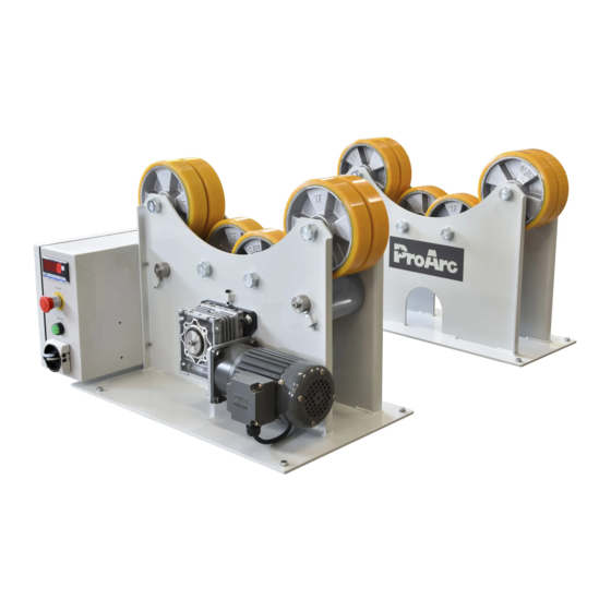
MODEL:TR ‒ 3504
TURNING ROLL (Digital)
Serial Number:200907003 ~ Later
th
Revised Date: Sep. 18
, 2020
UNITED PROARC CORPORATION
th
No. 3 Gungye 10
Road, Pingjen Ind. Park,
Tel No:886 3 4696600
Pingjen City, Taoyuan 324, Taiwan
Fax No:886 3 4694499
http: //www.proarc.com.tw
E-Mail: customerservice@proarc.com.tw
Advertisement
Table of Contents

Related Manuals for ProArc TR-3504

Summary of Contents for ProArc TR-3504
- Page 1 MODEL:TR ‒ 3504 TURNING ROLL (Digital) Serial Number:200907003 ~ Later Revised Date: Sep. 18 , 2020 UNITED PROARC CORPORATION No. 3 Gungye 10 Road, Pingjen Ind. Park, Tel No:886 3 4696600 Pingjen City, Taoyuan 324, Taiwan Fax No:886 3 4694499 http:...
-
Page 3: Table Of Contents
TABLE OF CONTENTS Introduction Instruction ....................i Safety precautions ................... ii Limited warranty ..................iii Specification & installation 1.1 Features .................... 1 1.2 Specification ..................2 1.3 Installation ..................3 Operation 2.1 Remote control instruction ..............4 Trouble shooting guide 3.1 Trouble shooting guide .............. - Page 4 If there is any damage, notify the carrier immediately to file a claim. Furnish complete information concerning damage claims or mistake(s) in shipment to United ProArc Corporation : No. 3 Gungye 10 Road, Pingjen Ind. Park, Pingjen City, Taoyuan 324, Taiwan. Include the equipment identification number along with a description of the parts in question.
-
Page 5: Safety Precautions
SAFETY PRECAUTIONS Operation and maintenance involves potential hazards. All operators and personnel should be alerted to possible hazards and precautions WARNING should be taken to prevent possible injury. Machine : Electrical safety ﹡ The counter, safety device against excess current and electrical installation, are compatible with its maximum power and its main voltage. - Page 6 SAFETY PRECAUTIONS * Often check the insulation and connection good state of apparatus and electrical Maintenance accessories : taps, appliance cords, coatings, switch, extension cords, etc. ﹡ Maintenance and repair of insulating coatings operations are very important. ﹡ Do repair with a specialist or better replace defective accessories. ﹡...
-
Page 7: Limited Warranty
UNITED PROARC’s obligation under this warranty policy is expressly limited to the replace or repair, at its option, of the defected part only. ProArc’s option to repair or replacement of a defected part under this warranty shall be based on FOB Taiwan basis. -
Page 9: Specification & Installation 1.1 Features
1.1 FEATURES Direct final positive gear drive. Roll work range, from 9mm to 1200mm diameter, without changing wheel center. “Forward / Stop / Reverse” switch with potentiometer for step less speed adjustment. Ideal where pipe works for welding. ... -
Page 10: Specification
1.2 SPECIFICATION Model Unit TR-3504 Power Input 1 Phase 220V 50/60Hz 3 Phase 460V 50/60Hz Rated Capacity NFB Capacity Turning Capacity 3,500 Load Capacity (Drive & Idler) 3,500 ψ9 ~ 1400 Diameter Range Speed Range mm/min 60 ~ 1200 Rotation Motor ψ200... -
Page 11: Installation
1.3 INSTALLATION Power Roll Idler Roll... -
Page 12: Operation 2.1 Remote Control Instruction
2.1 REMOTE CONTROL INSTRUCTION 1. Main power switch:System’s main power ‒ NFB switch (circuit breaker). 2. “Start” switch:Press to start the system – green light. 3. Remote control device: A. Speed meter. Shows the speed data (Hz.) B. Speed knob. To increase speed, turn clockwise. - Page 13 2.1 REMOTE CONTROL INSTRUCTION...
-
Page 14: Trouble Shooting Guide 3.1 Trouble Shooting Guide
3.1 TROUBLE SHOOTING GUIDE SYMPTOM POSSIBLE CAUSE / REMEDY A. NFB jumps off. To check the main circuit-disconnect or short. B. No power input. To inspect the AC power input voltage and phase. C. DC24V no output (a) To inspect and make sure the switching power supply input voltage is correct or not ? 1. - Page 15 3.1 TROUBLE SHOOTING GUIDE SYMPTOM POSSIBLE CAUSE / REMEDY A. Remote control breaks down. Please refer the item 6. B. Control PC board. Please refer the item 2. C. Inverter breaks down, no output. 5. The turntable has no movement. Please refer the item 3 &...
-
Page 16: Parts List 4.1.1 Parts List - Power Roll (Tr-3504P)
4.1.1 PARTS LIST ― POWER ROLL (TR-3504P) Item. Part No. Description Q’ty. Remark * 5041-1030000-10 PU roller with bearing earing Roll & B * 5041-1030100-10 PU roller * 0301-0403 Bearing 5045-1560100-10 Friction wheel 5045-1560200-10 Friction shaft 0301-0403 Deep-Groove ball bearing 0123-2000 Hex nut 0122-2000... -
Page 17: Parts List - Idler Roll (Tr-3504I)
4.1.2 PARTS LIST ― IDLER ROLL (TR 3504I) Item. Part No. Description Q’ty. Remark * 5041-1030000-10 PU roller with bearing earing Roll & B * 5041-1030100-10 PU roller 0301-0403 Bearing 5045-1540300-10 Screw 0123-2000 Hex nut 0122-2000 Spring washer * Recommended spare parts... -
Page 18: Parts List - Control Box
4.2 PARTS LIST ― CONTROL BOX Item. Part No. Description Q’ty. Remark 3061-1006 Line speed meter 3214-2002 E.S Push Button 3214-1005 Contact 3214-4006 Push button (w/ light) 3216-1003 Rotary switch 3323-0005 Power supply * 3224-1005 Magnetic contactor * 3221-2003 No Fuse breaker With AC220V 3221-3008 No Fuse breaker... -
Page 20: Circuit Diagram 5.1 Control Circuit
5.1 CONTROL CIRCUIT (1ψ220V) - Page 21 5.1 CONTROL CIRCUIT ( 3ψ380V / 415V / 460V )
- Page 22 5.1 CONTROL CIRCUIT (REMOTE CONTROL)
-
Page 23: Control System Box
5.2 CONTROL SYSTEM BOX 1 ψ 220V 3 ψ 380V~460V... -
Page 24: Appendix Inverter Settings
APPENDIX A : INVERTER SETTINGS 00:Drive Parameters. Setting Pr. No. Parameters Function Explanation Value 1:Write protection for Parameters 00-02 Parameters reset. 10:Reset all parameters to defaults. (Base frequency is 60 Hz) 00-06 Firmware version. Read only. 1.08 00-10 Control mode. 0:Speed control mode. - Page 25 APPENDIX A : INVERTER SETTINGS 02:Digital input / output Parameters. Setting Pr. No. Parameters Function Explanation Value 2:Two-wire mode 2, power on for 02-00 Two-wire / three-wire operation control. operation control. (M1:RUN/ STOP,M2:REV/FWD) 6:Zero speed including stop (Frequency 02-03 Multi-function input command 3 (MI3) command) 02-04 Multi-function input command 4 (MI4)
-
Page 26: Wiring Diagram
APPENDIX B : CIRCUIT (AC220V 1 PHASE) - Page 27 APPENDIX B : CIRCUIT (AC380/415V/460V 3 PHASE)