Table of Contents
Advertisement
Quick Links
OWNER'S MANUAL
RD-8428E
Important:Read these instructions before installing, operating or servicing this product.
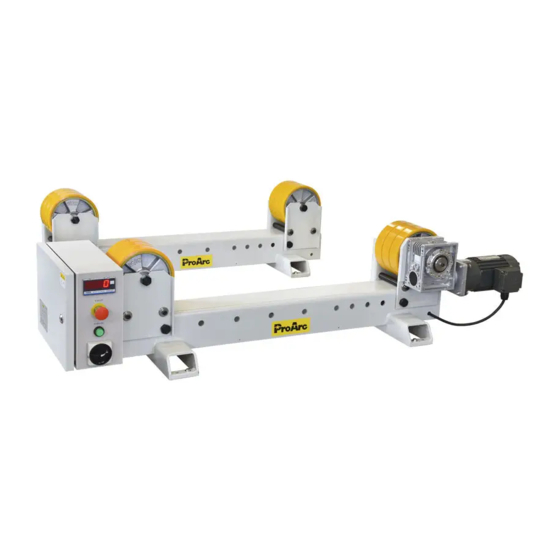
MODEL:TR-3500B / TR-6000B
Digital Turning Rollers
Serial number:1401013 ~ later
Date:Feb. 27, 2014
UNITED PROARC CORPORATION
th
No. 3 Gungye 10
Road, Pingjen Ind. Park,
Tel No:886 3 4696600
Pingjen City, Taoyuan 324, Taiwan
Fax No:886 3 4694499
http: //www.proarc.com.tw
E-Mail:
customerservice@proarc.com.tw
Advertisement
Table of Contents

Related Manuals for ProArc TR-3500B


Summary of Contents for ProArc TR-3500B
- Page 1 OWNER’S MANUAL RD-8428E Important:Read these instructions before installing, operating or servicing this product. MODEL:TR-3500B / TR-6000B Digital Turning Rollers Serial number:1401013 ~ later Date:Feb. 27, 2014 UNITED PROARC CORPORATION No. 3 Gungye 10 Road, Pingjen Ind. Park, Tel No:886 3 4696600 Pingjen City, Taoyuan 324, Taiwan Fax No:886 3 4694499...
- Page 2 PRIMARY POWER CONNECTION Read and understand this entire manual regarding the rules for users’ WARNING safety before installing, operating, or servicing the equipment. Please read this owner’s manual carefully before connection of the wires to AC power. Wrong connection may damage the equipment. Before connecting primary power, check the data plate to verify the voltage required by the TR-XX.
-
Page 3: Table Of Contents
TABLE OF CONTENTS Introduction Instruction ......................i Safety precautions ....................ii Limited warranty ....................iii General information 1.1 Introduction ..................... 1 1.2 Specification ....................2 Installation 2.1 Installation & adjustment ................. 3 Operation 3.1 Operation instruction ..................4 3.2 Remote control instruction ................6 Troubleshooting 4.1 Troubleshooting guide .................. - Page 4 If there is any damage, notify the carrier immediately to file a claim. Furnish complete information concerning damage claims or mistake(s) in shipment to United ProArc Corporation: No. 3 Gungye 10 Road, Pingjen Ind. Park, Pingjen City, Taoyuan 324, Taiwan. Include the equipment identification number along with a description of the parts in question.
-
Page 5: Safety Precautions
SAFETY PRECAUTIONS Operation and maintenance involves potential hazards. All operators WARNING and personnel should be alerted to possible hazards and precautions should be taken to prevent possible injury. Machine : Electrical safety ﹡ The counter, safety device against excess current and electrical installation, are compatible with its maximum power and its main voltage. - Page 6 SAFETY PRECAUTIONS ﹡ Gases and fumes produced during the plasma cutting or welding process can Gases and fumes be dangerous and hazardous to your health. ﹡ Ventilation must be adequate to remove gases and fumes during operation. ﹡ Keep all fumes and gases from the breathing area. ﹡...
-
Page 7: Limited Warranty
UNITED PROARC’s obligation under this warranty policy is expressly limited to the replace or repair, at its option, of the defected part only. ProArc’s option to repair or replacement of a defected part under this warranty shall be based on FOB Taiwan basis. - Page 9 1.1 INTRODUCTION Instruction ﹡ The turning rollers can be applied on round shaped work pieces, such as tanks, drums, pressure and cylindrical vessels and pipe to do the sequential circumferential rotation. ﹡ The turning roller can be associated with manual welding or the automatic welding. For example:manipulator.
-
Page 10: Specification
1.2 SPECIFICATION MODEL UNIT TR-3500B TR-6000B 1 Phase 220V ~ 240V 50 / 60Hz Power Input 3 Phase 460V 50 / 60Hz Rated capacity NFB capacity 6 / 2 6 / 2 Turning capacity 3500 6000 ψ50 ~ 3000 Diameter range (D) -
Page 11: Installation 2.1 Installation & Adjustment
2.1 INSTALLATION & ADJUSTMENT Instruction During installation, please pay attention to the parallelism and horizontal height of the bed of drive / idler. ﹡ When the ground is rugged, please adjust the screw of the base to make the height of bed horizontal and to prevent vibrations. Bed needs to be fixed on the ground to prevent any movement caused by vibration during operation. -
Page 12: Operation 3.1 Operation Instruction
3.1 OPERATION INSTRUCTION ﹡ Instruction Correct loading angle --- 40 º ~ 60 º . When the loading angle is incorrect, the following situations would occur: A. When the contact angle between work piece and turning roller is more than 60º, the roller would suffer from the improper squeeze or the work piece would be stuck between the rollers, which would cause the damage of the roller and shaft. - Page 13 3.1 OPERATION INSTRUCTION...
-
Page 14: Remote Control Instruction
3.2 REMOTE CONTROL INSTRUCTION 1. System power switch:System’s main power - NFB switch (circuit breaker). 2. “Start” switch:Press to start the system – green light. 3. While HP mode, the wheel speed is controlled by the adjustment knob on the remote pendent. The foot switch is only used to start / stop the rotation. -
Page 16: Troubleshooting 4.1 Troubleshooting Guide
4. 1 TROUBLESHOOTING GUIDE SYMPTOM POSSIBLE CAUSE / REMEDY (1.) After switch on, the power light A. NFB jumps off. doesn't lit To check the main circuit-disconnect or short. B. No power input. To inspect the AC power input voltage and phase. C. - Page 17 4.1 TROUBLE SHOOTING GUIDE SYMPTOM POSSIBLE CAUSE / REMEDY (6.) Remote switch has no action or A. Snap switch damaged. speed control knob disable. To check the snap switch connector is normal or not? And replace it. B. Potentiometer damaged. To measuring the potentiometer resistance (5KΩ) is normal or not? If yes, please change a new one.
- Page 18 5.1 PARTS LIST ─ CONTROL BOX Fig No. Part No. Description Q’ty. Remark 3061-1006 Line speed meter 3214-2002 ES Push Button 3214-1005 Contact 3214-4006 Push button (w/ light) 3216-1003 Rotaryes switch * 3323-0005 Power supply * 5015-5090000-30 Power supply clamping plate * 3224-1005 Magnetic contactor 3221-2001...
-
Page 19: Control System Box
5.2 PARTS LIST ─ TR-3500BP / TR-6000BP Q’ty. Fig No. Part No. Description Remark TR-3500BP TR-6000BP 5041-4010000-24 Machine bed ** 5041-3700010-20 Idler wheel ** 5041-4030010-20 Idler wheel ** 5041-3600010-22 Main wheel ** 5041-4060010-22 Main wheel ** 0353-0111 Worm reducer ** 0353-0114 Worm reducer * 0350-0019 Gear Motor... - Page 20 5.3 PARTS LIST ─ TR-3500BI / TR-6000BI Q’ty. Fig No. Part No. Description Remark TR-3500BI TR-6000BI 5041-4190000-10 Machine bed Idler wheel ** 5041-3700010-21 Idler wheel ** 5041-4030010-21 * Recommended spare parts ** Options...
- Page 21 5.4 PARTS LIST ─ TR-3500BP / TR-6000BP ( MAIN WHEEL ) Q’ty. Fig No. Part No. Description Remark TR-3500BP TR-6000BP 5041-4060000-13 Support plate (left) 5041-4070000-13 Support plate (right) * 5041-4110000-20 Joint-Bar 5041-4110100-20 Positioning bar ** 5041-3640000-21 Drive shaft ** 5041-4120100-21 Drive shaft ** 5041-3650000-21 Spacer...
- Page 22 5.5 PARTS LIST ─ TR-3500BI / TR-6000BI ( IDLER WHEEL ) Q’ty. Fig No. Part No. Description Remark TR-3500B TR-6000B 5041-4030000-21 Support plate (left) 5041-4040000-21 Support plate (right) * 5041-4110000-20 Joint-Bar * 5041-4110100-20 Positioning bar ** 5041-3230000-20 Spacer ** 5041-4110200-10...
- Page 23 6.1 CONTROL BOX CIRCUIT (1 ψ 220V)
- Page 24 6.1 CONTROL BOX CIRCUIT ( 3 ψ 380V / 415V / 460V )
- Page 25 6.1 CONTROL BOX CIRCUIT...
- Page 26 6.2 CONTROL SYSTEM BOX (1 ψ 220V)
- Page 27 6.2 CONTROL SYSTEM BOX (3 ψ 460V)
-
Page 28: Inside Input / Output Connect Interface
6.3 INSIDE INPUT/OUTPUT CONNECT INTERFACE : PCB1 J1 CONNECTOR POWER SUPPLY DESCRIPTION J2 CONNECTOR DESCRIPTION LINE METER PCB-CN12 DESCRIPTION IN (HI) IN(LO) POWER POWER J3 CONNECTOR INVERTER CTL DESCRIPTION JN2-5 INV1-F1 JN2-6 INV1-F2 CN3 CONNECTOR INVERTER 1 DESCRIPTION... - Page 29 6.3 INSIDE INPUT/OUTPUT CONNECT INTERFACE : PCB1 CN4 CONNECTOR INVERTER 1 DESCRIPTION +-10V +10V CN7 CONNECTOR HAND PENDANT DESCRIPTION AFM1 GND1 AVI1-HP 10V1 GND1 M10-HP ES-1 ES-2 CN8 CONNECTOR REMOTE FOOT SWITCH DESCRIPTION JN5-3 JN5-2 JN5-1 GND1 JN5-4 M10-RF JN5-5 GND1...
- Page 30 6.3 INSIDE INPUT/OUTPUT CONNECT INTERFACE : PCB1 CN10 CONNECTOR CN10 FRONT SW DESCRIPTION PB1-1 PB1-1 PB1-2 PB1-2 L1-1 L1-1 L1-2 L1-2 11 (Option) SW2-1 SW2-1 12 (Option) SW2-2 SW2-2 CN11 CONNECTOR CN11 DESCRIPTION...
-
Page 31: Input/Output Connect Interface
6.4 INPUT/OUTPUT CONNECT INTERFACE JN2 CONNECTOR PCB-J3 DESCRIPTION INV1-F1 INF1-F2 JN4 CONNECTOR PCB-CN7 DESCRIPTION AFM1 GND1 AVI1-HP 10V1 GND1 M10-HP ES-1 ES-2 JN5 CONNECTOR PCB-CN8 DESCRIPTION GND1 M10-RF GND1 GND1... - Page 32 APPENDIX A: INVERTER SETTINGS Item Name Setting Value Remark Pr00 Source of frequency command Pr01 Source of operation command Pr03 Maximum output frequency Pr04 Maximum voltage frequency Pr05 Maximum output voltage Pr06 Mid-Point frequency Pr07 Mid-Point voltage Pr08 Minimum output frequency Pr09 Minimum output voltage Pr10...
- Page 33 PD-6166...
-
Page 36: Revisions
REVISIONS Manual number Print data Changed page Revisions RD-8428E 2014, 03.07 RD-8428E 2017, 01.04 5.2 (P11) Revised No.2 and No.3 part no.
Need help?
Do you have a question about the TR-3500B and is the answer not in the manual?
Questions and answers