
Related Manuals for SOMA Pulsar-23


Summary of Contents for SOMA Pulsar-23
- Page 1 PULSAR 23 A Guidebook A Notebook A Reference Book The Pulsar-23 Notebook : Reference & Guide...
- Page 2 The Pulsar-23 Notebook : Reference & Guide...
-
Page 3: Table Of Contents
Contents Overview Sound Generators Looper & Clock Patching SHAOS & LFO Master Out & Effects External Control Technique Index The Pulsar-23 Notebook : Reference & Guide... - Page 4 The Pulsar-23 Notebook : Reference & Guide...
-
Page 5: Overview
It is therefore However the real power and beauty of strongly advised to approach Pulsar-23 with an Pulsar-23 is in the things that make it different open mind and embrace the innovation, unusual from a routine drum synth. While Pulsar-23 features and it’s almost endless options that can... - Page 6 NOTES This book sits alongside the existing SOMA quick start and official manual for Pulsar-23. It brings a different perspective to user experience and goes a little deeper on some of the unique functionality. The design means it acts as a reference, a guidebook and also a notebook with ‘designed in’...
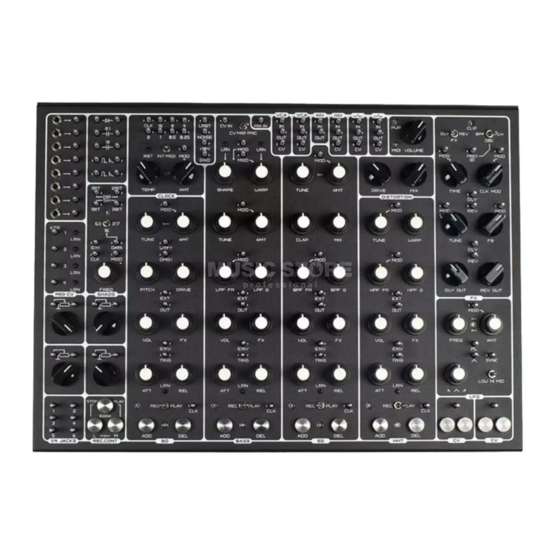
- Page 7 Overview 1.2 Hardware Overview Pulsar-23 is supplied, as well as the unit, with the 12V Power Supply Unit , 20 x 65mm alligator clip patch cables, 10 x 30mm alligator clip patch cables, soft travel case and packaging. MIDI 5 Pin DIN Input 6 x 1/4inch, Male Mono TR Jacks for external inputs and outputs.
- Page 8 2 CV Controls. CV generated by touch. Inverters Attenuators 2 Inverters, one is CV controlled. 4 Audio or CV controllers. Switches 1/4 Jack Connections 2, CV Controlled audio / CV switches. Patchbay to/from rear connectors. The Pulsar-23 Notebook : Reference & Guide...
- Page 9 A summary of some of the key differences from the norm will help to get to know Pulsar-23 and set the expectations for the onward journey. The available features don’t necessarily make an instrument better nor make it worse, they just make it different and each will fit based on individual preferences and needs.
- Page 10 While you may think this should be hidden at the back of this book, understanding the terminology associated with these topics and especially the Pulsar-23 will help unlock it’s power and performance. It makes sense to become familiar early with the essential terms to help embed into your workflow.
- Page 11 MIDI Random Note Generator shift registers. Input is applied using 5 Pin MIDI DIN connection. Pulsar-23 also has a LRN - Learn function to map Sound Generators: Pulsar-23 has 4 dedicated incoming MIDI CC to it’s controls and functions.
- Page 12 Overview 1.6 Structure of Pulsar-23 NOTES While Pulsar-23 is very different to the traditional drum machine it follows some core principles of synthesis especially with respect to the sound sources. In addition the workflow and operation heavily relates to the principles of modular synthesis;...
- Page 13 Overview NOTES While Pulsar-23 has a series of modules with an almost endless set of patching configurations. This encourages wild and crazy experimentation. However, there is still a core underlying structure when unpatched. This allows building around the default ‘in the box’ wired routings.
- Page 14 NOTES The Pulsar-23 Notebook : Reference & Guide...
-
Page 15: Sound Generators
Multiple patch points allow for an Remember that the Pulsar-23 has no hard expansive range of modulation and routing rules between CV control and Audio patching. - Page 16 2.1 Sound Module Overview NOTES Pulsar-23 has 4 specific audio generation modules, each with a unique sound engine and a feature set for sound design and shaping. Others can of course generate audio but these 4 audio modules are covered here as the primary audio sources.
- Page 17 The strongest signal (highest voltage) will determine which trigger takes precedence Patched MIDI ‘TRIG’ [ADD] {PLAY} Sensor Button Loop Recorder Core Sound Output Envelope Source Parameters The length of the sound is determined by duration that the trigger is present The Pulsar-23 Notebook : Reference & Guide...
- Page 18 This is also based on the duration of the trigger state. An AR - Attack / Release envelope type is used in Pulsar-23, a model often used for drum sounds TRIG...
- Page 19 (REL) knob. The effect will be heard when triggering. 5. This is an incremental and iterative process so tweak and adjust until a desired state is found. This may be revised during further sound design and development adjustments of other parameters. The Pulsar-23 Notebook : Reference & Guide...
- Page 20 For example light or hard touch on a piano key will often correspond to its loudness. Pulsar-23 can recognise velocity, but is only controllable from an external MIDI controller. Internally, Pulsar-23 can trigger the sound generators at 3 manually selectable velocity levels.
- Page 21 8. If loop recording, maximum velocity level is also applied and recorded when only using the [ADD] button. Velocity can be changed by overdub recording in the loop recorder. The Pulsar-23 Notebook : Reference & Guide...
- Page 22 Example Sound source and generator. Each module will have some audio and modulation features specifically aimed at developing the Pulsar-23 character sound, timbre and tone associated with it’s unique synthesis function. The VCA audio and envelope parameters. These functions such as the volume level, FX send, envelope parameters are replicated discretely per module.
- Page 23 Input for externally clocking the loop recorder channel. This will replace the internal clock. ADD Button Sensor Manual trigger for playing or recording drum hits. DEL Button Sensor Manual trigger for deleting / muting recorded drum hits. The Pulsar-23 Notebook : Reference & Guide...
- Page 24 While this function is based on classic analog bass drums, there are many more avenues and options to explore and experiment with than just the traditional features. BD Bass Drum The Pulsar-23 Notebook : Reference & Guide...
- Page 25 Discrete clock point Input for alternative, external clocking for loop recorder. ADD Button Sensor Manual trigger for playing or recording drum hits. DEL Button Sensor Manual trigger for deleting / muting recorded drum hits. The Pulsar-23 Notebook : Reference & Guide...
- Page 26 Voltage Controlled Oscillator OMG! PITCH Envelope WTF! DRIVE Wave Shaping MIDI Volume Envelope TRIG Voltage Controlled Amplifier Send Mix Bus KNOB Function with control Italics Internal Functions CAPITALS Pin In / Out (Arrow) The Pulsar-23 Notebook : Reference & Guide...
- Page 27 Sound Generators NOTES BD Sound Design Examples. Hard Kick Electronic Kick Ambient Bass Drum Aggressive BD Sub Bass The Pulsar-23 Notebook : Reference & Guide...
- Page 28 DCO - Digitally Controlled Oscillator which then passes through an analog signal chain including a LPF - Low Pass Filter. The mode switch selects pitch control from CV or MIDI or the percussion PRC mode. Bass Synth The Pulsar-23 Notebook : Reference & Guide...
- Page 29 Discrete clock point Input for alternative, external clocking for loop recorder. ADD Button Sensor Manual trigger for playing or recording drum hits. DEL Button Sensor Manual trigger for deleting / muting recorded drum hits. The Pulsar-23 Notebook : Reference & Guide...
- Page 30 ‘MOD’ : Phase modulation of the DCO ‘MOD’ : Sidechain trigger input. from a CV input plus control over the Controlled ‘ducking’ inversion of DCO modulation amount. based on the input shape e.g. envelope. The Pulsar-23 Notebook : Reference & Guide...
- Page 31 LPF Q Low Pass Filter Low Pass Filter Frequency Resonance MIDI Volume Envelope TRIG Voltage Controlled Amplifier Send Mix Bus KNOB Function with control Italics Internal Functions CAPITALS Pin In / Out (Arrow) The Pulsar-23 Notebook : Reference & Guide...
- Page 32 LPF Q Low Pass Filter Low Pass Filter Frequency Resonance MIDI Volume Envelope TRIG Voltage Controlled Amplifier Send Mix Bus KNOB Function with control Italics Internal Functions CAPITALS Pin In / Out (Arrow) The Pulsar-23 Notebook : Reference & Guide...
- Page 33 Sound Generators NOTES BASS Sound Design Examples. Moody Bass Smooth Bass Gnarly Bass Boomy Bass Drum Screetch Steam Train The Pulsar-23 Notebook : Reference & Guide...
- Page 34 The SD module represents the snare drum as well as integrated clap synthesis. This synth is built on a unique spectrum controlled noise generator which is the sound source. The analog signal path includes a BPF - Band Pass Filter. SD Snare Drum The Pulsar-23 Notebook : Reference & Guide...
- Page 35 Discrete clock point Input for alternative, external clocking for loop recorder. ADD Button Sensor Manual trigger for playing or recording drum hits. DEL Button Sensor Manual trigger for deleting / muting recorded drum hits. The Pulsar-23 Notebook : Reference & Guide...
- Page 36 Add* TRIG Voltage Controlled Amplifier Send Mix Bus * Clap only operates with ‘ADD’ and MIDI, not the ‘TRIG’ Pin. KNOB Function with control Italics Internal Functions CAPITALS Pin In / Out (Arrow) The Pulsar-23 Notebook : Reference & Guide...
- Page 37 Sound Generators NOTES SD Sound Design Examples. (Clap does not activate from the ‘TRIG’ pin) Single Clap Flam Snare Classic Snare Echo Clap Noisy Snare Rim Snare The Pulsar-23 Notebook : Reference & Guide...
- Page 38 The final sound generator is the HHT Synthesis module which represents Hi Hat, Shaker and Cymbal sounds again using a noise generator. The analog signal chain includes a HPF - High Pass Filter. HHT Hi Hat The Pulsar-23 Notebook : Reference & Guide...
- Page 39 Input for externally clocking the loop recorder channel. This will replace the internal clock. ADD Button Sensor Manual trigger for playing or recording drum hits. DEL Button Sensor Manual trigger for deleting / muting recorded drum hits. The Pulsar-23 Notebook : Reference & Guide...
- Page 40 HPF Q High Pass Filter High Pass Filter Frequency Resonance MIDI Volume Envelope TRIG Voltage Controlled Amplifier Send Mix Bus KNOB Function with control Italics Internal Functions CAPITALS Pin In / Out (Arrow) The Pulsar-23 Notebook : Reference & Guide...
- Page 41 Sound Generators NOTES HHT Sound Design Examples. Shaker Closed Hat Open Hat Crash Rattle The Pulsar-23 Notebook : Reference & Guide...
- Page 42 Human hearing operates in the 20Hz to 20KHz range and therefore this is the typical range of a filter. Pulsar-23 also uses filtering as part of the sound shaping and construction of sounds for the Bass synth, Snare Drum and Hi Hat Drum. These help to polarise the focus of the sound in the spectrum and avoids frequency clashes with others in the mix.
- Page 43 FX Send The diagram shows a simplified illustration of the output summing principles. Other elements that are not show here such as distortion also is included in the audio master out. The Pulsar-23 Notebook : Reference & Guide...
- Page 44 Sound Generators 2.10 Noise NOTES Pulsar-23 has four dedicated sound modules which operate for BD, Bass, SD and HHT. In addition a dedicated noise source is provided which operates independently from the four sound modules. This is a patchable output pin and is located along with the power and looper reset functions.
- Page 45 Sound Generators 2.11 Sound as a Control Source NOTES Pulsar-23 is an extremely versatile device. The ability to use audio as a modulation source is possible. It is worth trying various patch combinations and discovering some of the secrets it holds.
- Page 46 2.12 Control as a Sound Source NOTES Its been said that a unique feature of Pulsar-23 is the ability to use audio as a modulation source but also how control can also be used to generate sound. In the true spirit of Pulsar-23, experimentation and exploration by trying things is a journey worth taking.
- Page 47 The frequencies are normally too low to operate in the audible frequency range 20Hz and above. However the Pulsar-23 LFO can operate at higher audio frequencies and can be patched as a traditional oscillator sound source.
- Page 48 NOTES The Pulsar-23 Notebook : Reference & Guide...
-
Page 49: Looper & Clock
Pulsar-23 and at the heart of creating full songs sequencing, the looper recorder operates sequenced patterns. more like a classic tape recorder, capturing application of these functions, just like other and overdubbing drum patterns as played. - Page 50 3.1 Master Clock Module Overview NOTES The master clock module is central to Pulsar-23’s timing and tempo. The role of a clock is important in modular based systems to ensure all functions operate in time together. Timing pulses are sent to enable this synchronisation across functions and can also be used to trigger drum hits and events.
- Page 51 The master clock module has an internal clock generator which, by default is used in Pulsar-23. There are also options to use an externally connected MIDI clock or patch an external clock pulse input to the ‘CLK’ Pin. This is selectable on the ‘INT MIDI’...
- Page 52 ‘click’. • The cycles in Pulsar-23 will have a rising edge and a falling edge in each cycle. When patching a clock divider to the ‘MIX IN’ to operate as a metronome, 2 triggers will be output per cycle.
- Page 53 The metronome would ‘click’ at 2x the division value. Therefore set the division to half the required frequency i.e. set to 2 for a metronome at every quarter note interval. The Pulsar-23 Notebook : Reference & Guide...
- Page 54 Note Note Note Note 32 Ticks 32 Ticks 32 Ticks 32 Ticks 1 Tick = 1/32 Note 1 Tick = 1/32 Note 1 Tick = 1/32 Note 1 Tick = 1/32 Note 0.25 The Pulsar-23 Notebook : Reference & Guide...
- Page 55 NOTES The master clock module is very accurate and operates to trigger events in Pulsar-23 or for other external equipment. The clock also determines the looper recorder length. Note that there is no numerical indicator of tempo in BPM, the clock LED is the visual indicator of timing. Looper length is a maximum of 4 bars and is determined as a duration in seconds or minutes by the tempo.
- Page 56 Summing Clock Pulses Multiple clock pulse outputs can be connected together. The resulting clock will generate a more interesting and complex pattern, ideal for triggering a drum module or as a modulation source. The Pulsar-23 Notebook : Reference & Guide...
- Page 57 The frequency governed by the tempo and clock divider. Try using the clocks ‘16’ output divider and patch to the HHAT without the pulse transformer. The shorter pulses should be ideal for hi hats. The Pulsar-23 Notebook : Reference & Guide...
- Page 58 The master clock can be controlled externally from a separate device or it can even be controlled by using another Pulsar-23 function such as the SHAOS or LFO module. The clock has intelligence to recognise the incoming pulses when patched to the ‘CLK’...
- Page 59 The amount of adjustment can be made and other dividers individually or patched together with other dividers to generate interesting patterns. The ‘AMT’ knob will control the amount of modulation applied. The Pulsar-23 Notebook : Reference & Guide...
- Page 60 BD will trigger on beat and the SD delayed to trigger on the off beat. 16 note hats will be straight. Tempo will adjust the overall speed / timing. Try using the looper recorder to lay a bass line over the beat. The Pulsar-23 Notebook : Reference & Guide...
- Page 61 “roaming” patch cable or by a manual single hand patch to trigger from the ‘GND” pin to affect clocks in an ad hoc way. This can throw them out of synchronisation and create interesting and experimental patterns. Press the RST Reset button to reset the Master Clock synchronisation. The Pulsar-23 Notebook : Reference & Guide...
- Page 62 Each of the 4 sound generator modules has its own looper recorder channel. Rather than step recording with grid quantised programming, Pulsar-23 operates more like a tape based loop recorder using the [ADD] and [DEL] buttons. Each looper recorder operates independently and by default is controlled and ‘hard wired’...
- Page 63 The looper records start of note events, length and velocity. In reality this is managed by the Pulsar-23 memory, but it is useful to illustrate this in the same way as a continuous tape loop with real time recording and overdubbing.
- Page 64 Holding all three buttons simultaneously + ADD or DEL of a selected channel will quantize recorded events. The looper will stop and need restarting with BANK + M + ADD / DEL of BD to continue. The Pulsar-23 Notebook : Reference & Guide...
- Page 65 Will erase any existing note events while holding DEL as the loop plays. Quantize 1/16 Hold Hold Hold Will quantize to 1/16 intervals, the notes notes recorded for the selected ADD or DEL Channel. The Pulsar-23 Notebook : Reference & Guide...
- Page 66 Option to patch an alternative clock to LR ‘CLK’ Pin. This will override the internal clock if a rising edge is greater than 2V. Individual LR timing is therefore possible. Function is the same for all four Looper Recorders. BASS The Pulsar-23 Notebook : Reference & Guide...
- Page 67 Example; Patch clock divider ‘1’ to ‘LRST’ to shorten looper length Example; Patch clock divider ‘0.5’ to ‘LRST’ to adjust looper length Example; Patch clock divider ‘2’ to ‘LRST’ to adjust looper length The Pulsar-23 Notebook : Reference & Guide...
- Page 68 Pulsar-23 can store the the 4 recorded looper channels for each module, into a bank. Pulsar-23 has 4 banks, each of which can be also be selected by using the 4 drum module controls. The memory for the looper is volatile, meaning that once power to Pulsar-23 is removed, the memory is cleared and all loops are lost.
- Page 69 5. To copy only part of the loop, Hold [BANK] + [ADD] + [DEL] on the destination bank, represented by the sound generator module selected. Keep the buttons held for the length required to paste part of the copied bank into the new location. The Pulsar-23 Notebook : Reference & Guide...
- Page 70 Pulsar-23 has three internal velocity settings when playing or recording note events. The REC CONT buttons act as modifiers for velocity. In addition Pulsar-23 recognises the full range of note velocity from a connected external MIDI controller.
- Page 71 5. Stopping the master clock or grounding the module ‘CLK’ will also stop the looper. To ground the clock, patch by cable ‘GND’ to the specific sound generator module ‘CLK’. The Pulsar-23 Notebook : Reference & Guide...
- Page 72 3.12 Loop Recording Workflow NOTES Of course individual producers and musicians will develop their own work flow when working with Pulsar-23. A basic example workflow to get started may help identify some key steps. Start Set Master Clock Tempo to desired speed.
- Page 73 It is also an output. Any manual trigger from the [ADD] button or the looper recorder will also output on the ‘TRIG’ Pin. This means loops recorded on one module can trigger another. Try the circuit bending capacitors in-between patching the ‘TRIG’ Pins. The Pulsar-23 Notebook : Reference & Guide...
- Page 74 NOTES The Pulsar-23 Notebook : Reference & Guide...
-
Page 75: Patching
Take care when using patch cables as fundamental in unlocking the full potential of they can easily get caught under knobs and Pulsar-23 and is a normal and expected part of around pins. Also patching can be made by the workflow and the onward creative journey. - Page 76 Patch Pins Each Pulsar-23 patch point uses a metal pin which extrudes above the top panel face plate. These can be used to clip the alligator cable or to connect by touch to another patch point. There are 119 patch pins on the top panel.
- Page 77 Generally this offers multiple connections to the same point and makes the patching accessible to touch. In addition the cost and size of the Pulsar-23 is improved especially due to the number of patch points provided. Finally the reliability of patch pins is higher than with TS jack sockets.
- Page 78 NOTES Patch pins can represent an input to a function, output from a function or both. In Pulsar-23 audio and control can be cross patched. This is great for creative sound design. The Pulsar-23 front panel is labelled to indicate the input / output function using an arrow tag left or right of the pin.
- Page 79 This is more common in melodic synthesizers where notes and chord envelopes are sustained. Note On Note Off Level The Pulsar-23 Notebook : Reference & Guide...
- Page 80 This is the primary control method used in modular systems and of course Pulsar-23. Remember that uniquely in Pulsar-23, control and audio can be patched together to explore new sound and control possibilities. Various voltage levels can be found in different modular setups and it is useful to understand these and their differences.
- Page 81 +5V and 0 to 5V ranges to the less common 0 to 8V. In Pulsar-23 case both audio and the controls operate across a 0 to 10V range to allow for cross connections. The real consideration is the match up between devices and functions and of course the voltage ranges.
- Page 82 4.6 Patch Bay - Eurorack to Patch Pin NOTES Pulsar-23 recognises the importance of interfacing to Eurorack systems as well as other CV and Trigger based gear. As such an 8 channel, 3.5mm Jack to Patch pin patch bay is provided. This does not in itself offer any control or audio features but simply allows the conversation from the jack plug format to allow connection to patch pins.
- Page 83 External Eurorack Example The example shows a Eurorack processor, Modbap Modular Per4mer triggered from Pulsar-23 SD. This will affect the routed HHT drum module audio which is processed by Per4mer before returning it into Pulsar-23.The Patch bay converts from mini jack to the patch pin format in Pulsar-23.
- Page 84 Connecting the alligator clip to the TS Jack TIP also makes the connection Note: The patch bay also acts as the ground connection between external gear and Pulsar-23. Ensure at least one signal is connected through the patch bay when connecting between external devices and Pulsar-23.
- Page 85 This allows each channel to have more precise audio control through the mixer and to any connected monitoring systems / speakers. Effects could also be connected in the set up.. The Pulsar-23 Notebook : Reference & Guide...
- Page 86 Example: External Send Effects The example shows an external send effect. The BD drum module can individually be sent as audio output to an external effect e.g. reverb and returned to Pulsar-23. The amount of send can be controlled with an attenuator.
- Page 87 4.8 Attenuators NOTES Pulsar-23 has 4 attenuators which can be patched to various functions. The role of an attenuator is to control the level of an audio or control signal. Control is performed manually using the potentiometer rotary control knob.
- Page 88 Connection pin for audio master mix input Although not essential, it is good practice to patch the ‘MIX IN’ via a Attenuator to allow good control over the signal level sent to the main mix. The Pulsar-23 Notebook : Reference & Guide...
- Page 89 4.10 VCA NOTES A Voltage Controlled Amplifier, also called VCA, is a function that adjusts the gain of a signal automatically using a control voltage. Pulsar-23 has two independent VCA’s and they can control either audio or control signals. Item...
- Page 90 NOTES An inverter basically takes the input and inverts it at the output. There are two inverters available in Pulsar-23, one is controllable by CV to invert trigger signals and the other is fixed, non-controllable for audio and control signal inversion.
- Page 91 Patching 4.12 Switches NOTES Two identical voltage controlled switches are provided in Pulsar-23 that can switch audio and control signals. Voltages greater than +5V will turn the switch on and below will turn it off. Item Function Label Control Description...
- Page 92 Circuit bending is the technical art of physically modifying circuitry to alter the sound or a function. This may seem daunting unless you’re an engineer or an electronics technician. Pulsar-23 provides the ability for circuit bending by the patching of on board components such as resistors, capacitors and diodes.
- Page 93 Most capacitors are non-polarised as per the Pulsar-23 although some are. Often capacitors are found in power circuitry to help maintain, regulate and smooth voltage levels, to retain memory and to remove electrical noise.
- Page 94 This is especially useful for a semi-modular drum machine where short pulse triggers are applied to drum hits. Typically the gate will trigger each drum module’s envelope. In Pulsar-23 a common application is to use this with the clock divider.
- Page 95 Note that when patching between external Eurorack or desktop devices at least one connection should be made between the devices using the Pulsar-23 Eurorack 3.5mm Patch Bay or the 1/4 Jack Patch bay. Essentially to avoid unwanted electrical noise especially in the audio signal it is technically good practice to ensure all devices are connected to a common ground.
- Page 96 4.15 Dynamic Touch Sensors NOTES Pulsar-23 uses less conventional technology in its human interface. There is no better example of this than the dynamic touch sensors which are used to generate a manual modulation voltage. These are paired sensors which when both are touched by hand generate a voltage between 0-10V.
- Page 97 3. Release the touch from the sensors to stop the CV modulation change. Various modulation sources can be tried for the dynamic sensor output voltage. Dynamic sensor manipulated by touch and generates a voltage at the CV output pin. The Pulsar-23 Notebook : Reference & Guide...
- Page 98 NOTES The Pulsar-23 Notebook : Reference & Guide...
-
Page 99: Shaos & Lfo
The LFO and SHAOS units are Almost all of Pulsar-23’s features are open as integral in the array of options available for a modulation source or destination. Patching... - Page 100 Freq CV input for frequency modulation control. Modulation Note that while SHAOS is essentially a modulation source it can also operate at audio range and as such be used as a sound generator. The Pulsar-23 Notebook : Reference & Guide...
- Page 101 The internal clock will perform this function normally by default if no input is connected to ‘S/H”. Each pulse will trigger the sampling and holding of the pseudo-random sequencer. The 1 BIT and 3 BIT S/H outputs are synchronised to any S/H input. The Pulsar-23 Notebook : Reference & Guide...
- Page 102 Manual recording of pulses into memory can be done through the ‘DATA’ input switched in {16} Mode. Tapping to patch alternatively between the ‘+10V’ and ‘GND’ to ‘DATA’ will record pulses into the 16 step memory. This will record, evolve and drive the output patterns. The Pulsar-23 Notebook : Reference & Guide...
- Page 103 S&H outputs. Also the state, based on the bits, will determine a level which can control CV as a source. The Pulsar-23 Notebook : Reference & Guide...
- Page 104 Whether the triangle or square wave output is used in the audio range the LFO (TRIANGLE) shape and (AMT) will affect the audio as well as the (FREQ) control setting. The Pulsar-23 Notebook : Reference & Guide...
- Page 105 The LFO can also be used as an additional variable clock and can offer some interesting patch options when used for example to trigger or independently clock sound modules or drive the SHAOS S/H clock. The Pulsar-23 Notebook : Reference & Guide...
- Page 106 NOTES The Pulsar-23 Notebook : Reference & Guide...
-
Page 107: Master Out & Effects
Master Out & Effects Pulsar-23 operates in mono with a single A delay is based on delayed output fed back into output volume control for the mono output and the input. This creates an echo like effect. headphones, which are dual mono. Audio can... - Page 108 Adjusts the volume level of the main output and headphones output. MIDI Input MIDI Indicates MIDI input activity. Green LED indicates incoming MIDI data which is assigned to a control. Red LED indicates incoming MIDI but is unassigned. The Pulsar-23 Notebook : Reference & Guide...
- Page 109 Outputs can also be patched to the ¼ inch outputs and bypass the main output. This will allow better control for example with an external mixer if required. Summing Bus Distortion Main Out (All drum channels and FX returns) The Pulsar-23 Notebook : Reference & Guide...
- Page 110 Master Out & Effects 6.3 FX Overview NOTES Pulsar-23 has an FX section containing two effects each with multiple configurations. The configurations, known as operating modes determines how the effect operates and also the role of the controls. Sound Module ‘FX’...
- Page 111 Knob Level of delay returned to the main mix. Reverb Output Output of the reverb audio. Ideal for external mixing. Reverb Output REV OUT Knob Level of reverb returned to the main mix. The Pulsar-23 Notebook : Reference & Guide...
- Page 112 Delay is a classic time based effect that delays an input at the output and when this is fed back into the input can create long echo style effects. Pulsar-23 applies classic principles plus a unique set of operational modes and configurations within channel 1 of the FX module.
- Page 113 The pitch interval in the feedback is 1 Tap Delay Shifter adjusted by using the ‘TUNE’ knob when in PCH operating mode. Voltage on the ‘MAD!’ Pin causes DSP Mad! Tune madness. +10V for permanent chaos. The Pulsar-23 Notebook : Reference & Guide...
- Page 114 Reverb is also a classic time based effect that represents the space or room dynamics where audio waves would reflect and bounce from walls and objects generating extended sound characteristics. Pulsar-23 applies the classic principles but with a unique set of operational modes and configurations in channel 2 of the FX module.
- Page 115 The pitch interval in the feedback is Shifter adjusted by using the ‘TUNE’ knob when in PCH operating mode. Voltage on the ‘MAD!’ Pin causes DSP Mad! Tune madness. +10V for permanent chaos. The Pulsar-23 Notebook : Reference & Guide...
- Page 116 For example set FX to {DLY} and adjust the sound module (FX) knob to send from each sound generator. Also use the sound output patched to ‘REV’ Input to simultaneously use the reverb effect. The Pulsar-23 Notebook : Reference & Guide...
- Page 117 {DBL} operating mode is selected Headphone Both delay and reverb FX can also be routed out using the FX pins. The ¼” jacks can be used to connect external gear Left Right The Pulsar-23 Notebook : Reference & Guide...
- Page 118 NOTES The Pulsar-23 Notebook : Reference & Guide...
-
Page 119: External Control
External Control There are many options for interfacing DIN style connectors and this is the interface Pulsar-23 to other gear with built in patch bays applied in Pulsar-23 where a MIDI input is to make the process simple. There are two available on the rear of the unit. - Page 120 7.1 MIDI Definitions NOTES To clarify some of the terminology and technology around MIDI with respect to Pulsar-23 a summary of key definitions is provided. Pulsar-23 uses a direct MIDI input. MIDI over USB is not possible. 5 PIN MIDI...
- Page 121 7.2 MIDI Connections NOTES The 5 Pin MIDI Input connection is located on the rear of Pulsar-23. This uses a standard MIDI DIN cable and easily connected between other gear. Connect Pulsar-23 from the MIDI Out or MIDI Thru of an external device.
- Page 122 NOTES The implementation of MIDI is based on control from an external device to the Pulsar-23 using MIDI in. Note and CC based data can be learnt within Pulsar-23, which essentially assigns the learnt function to the external controller input.
- Page 123 Maps the external MIDI device to CV pin 3. CV Channel 4 Maps the external MIDI device to CV pin 4. Portamento of BASS Module. Pre-defined MIDI CC. Pitch Bend of BASS Module. Pre-defined MIDI CC. The Pulsar-23 Notebook : Reference & Guide...
- Page 124 For example, hold LRN buttons for both the WARP and SHAPE at the same time. 2. All MIDI triggers in Pulsar-23 will be halted. This is useful if MIDI inputs hang or the MIDI system freezes.
- Page 125 3. Set the ‘INT MIDI’ Switch located in the master clock module to the left, {MIDI} position. This sets Pulsar-23 to use the clock received from the MIDI in device.
- Page 126 MIDI configuration of the device. 3. Press and hold the LRN button at the bottom of a Pulsar-23, drum module to ensure it is ready to map from the connected incoming controller MIDI.
- Page 127 CC is mapped using the LRN button. In this example the rotary control would generate the CC messages. Note On / Off messages plus velocity, will be received by Pulsar-23 for the note envelope once the note is mapped using the LRN button. In this example the pad would generate a note on / off message for triggering the drum module envelope only for the individual pad.
- Page 128 Button Hold and adjust an external MIDI CC input to map to the module SHAPE control. Warp Learn Button Hold and trigger an external MIDI input to map to the module WARP control. The Pulsar-23 Notebook : Reference & Guide...
- Page 129 External Controllers learnt by the BASS Module. Continuous CC controller message, will be received by Pulsar-23 for Pitch Bend and also CC05 for Portamento. Dedicated LRN buttons can map CC to the SHAPE and WARP controls on the BASS Module.
- Page 130 MIDI channels. 4. Press and hold the LRN button in the lower part of a Pulsar-23 BASS module to ensure it is ready to map from the connected incoming controller MIDI.
- Page 131 ▌ MIDI LEARN FOR THE SHAPE FUNCTION 1. Press and hold the LRN button in the upper left part of the Pulsar-23 BASS module. This is for the SHAPE function to ensure it is ready to map from the connected incoming controller MIDI.
- Page 132 While there are a limited number of predefined mappings for MIDI to Pulsar-23, this can be extended by using the MIDI to CV Converter patch bay. This allows up to four MIDI inputs to be learnt on a patch pin and then physically patched with alligator cables to a function in Pulsar-23.
- Page 133 This is the preferred option and connects ground signals between the systems. • The voltage range of 0-10V to / from Pulsar-23 to the range specific for the connected Eurorack module. This should be generally OK for triggers but outcomes may be less predictable for CV control.
- Page 134 7.9 Eurorack Voltage Conversion NOTES As stated, Pulsar-23 uses 0-10V control signal ranges. This is not a Eurorack standard but in many cases will provide some level of control. If a more precise range is required there are options to convert, or at least re- range to a Eurorack standard.
- Page 135 The ‘INT MIDI’ Switch set centrally to {EXT} for external clock The primary lead clock, in this example Pam’s, would need to account for Pulsar-23’s 128 Tick resolution in order to match Pulsar-23’s tempo as secondary follower. In this example the square wave output is set to a x8 modifier to ensure the tempo match.
- Page 136 The ‘INT MIDI’ Switch set left to {INT} internal clock The primary lead clock, in this example Pulsar-23 will generate a clock based on its 128 Tick resolution. In order to match Pulsar-23’s tempo as secondary follower, Pam’s clock needs to know ticks per quarter note, called PPQN (Pulses Per Quarter Note). In this example hold Pam’s ‘program’...
- Page 137 / to alligator clips is advised as this also grounds the connection between Pulsar-23 and the rack. A typical example is to use a Eurorack sequencer for controlling the Pulsar-23 and offer a more traditional grid based pattern generation. Pulsar-23 is the primarily lead clock for this example but it makes sense for Ground Control to lead the clock.
- Page 138 The development of iPad based music apps has improved significantly in the past few years. So much so that an iPad now can be considered an serious option in a multi device setup. Pulsar-23 benefits greatly from this when interfacing an iPad over MIDI and also by routing audio.
- Page 139 Audio chain would route Pulsar-23 audio it’s MIDI input. The messages from iPad are output, through the plug-in chain in AUM. This assigned in Pulsar-23 using ‘LRN’. This could will allow additional processing and effects to be as simple as iPad keyboard or sequencing be added before channeling the audio out to using an arpeggiator.
- Page 140 NOTES The Pulsar-23 Notebook : Reference & Guide...
-
Page 141: Technique
These are starting points in patch creation you, as a Pulsar-23 musician or producer, take where you can build and extend your journey a step nearer to your personal destination. - Page 142 In its purest form the controller is a ‘modulator’ and destination is called a ‘carrier’. FM can create unique metal-like sounds. Pulsar-23 has the ability to emulate the principles of FM synthesis, in this case using the LFO as a Modulator. This patch can be expanded and is a starting point to develop an FM orientated design.
- Page 143 The VCA CV input uses an envelope. In this example the triggering the HHT envelope output is used to shape and activate the sound using it’s ‘ATT’ - Attack and ‘REL’ - Release. Envelope The Pulsar-23 Notebook : Reference & Guide...
- Page 144 174.61 164.81 155.56 146.83 138.59 130.81 123.47 116.54 110.00 103.83 97.999 92.499 87.307 82.407 77.782 73.416 69.296 65.406 61.735 58.271 55.000 51.913 48.999 46.249 43.654 41.203 38.891 36.708 34.648 32.703 30.868 29.135 27.500 The Pulsar-23 Notebook : Reference & Guide...
- Page 145 This is also called ducking and can be emulated using an inverter and VCA in Pulsar-23. Using BD as the sidechain trigger, patch the BD ‘ENV’ envelope out to the Inverter INV, Input.
- Page 146 Connect the BD (or any other module) ‘ENV’ Output to the Tune ‘MOD’ Pin. The ‘ATT’ - Attack and ‘REL’ - Release can be tuned to suit the drop style. The settings are important and the PITCH specifically affects the sound. The Pulsar-23 Notebook : Reference & Guide...
- Page 147 NOTES Patch Name: Droplets Its easy to see Pulsar-23 as an aggressive analog drum machine, but there can be some ambient and subtle sound designs with the right patch focus and parameter settings. The real key to this patch is the modulation used on the clock, FX and the HHT module especially when pinging the filter.
- Page 148 Connect the BD (or any other module) ‘ENV’ Output to the FX CLOCK MOD, ‘MOD’ Pin. Set the amount of modulation from the ‘CLOCK MOD to 4 O’Clock. Set parameters as illustrated. Trigger the BD module. Optionally, try the same patch with the SD module envelope. The Pulsar-23 Notebook : Reference & Guide...
- Page 149 8.7 Bright Pings NOTES Patch Name: Sparkles Evolving percussive soundscapes is possible in Pulsar-23. This patch creates a wash of sparkly pings and shows off the generative nature of SHAOS. Reverb fills close out the space with an ambient texture.
- Page 150 1-Bit output is used to control the inverter and the hat pattern. Switching between 217, 63 and then back to 16 will define the pattern. For synchronisation the clock ‘CLK’ is connected to the SHAOS ‘CLK’. The Pulsar-23 Notebook : Reference & Guide...
- Page 151 8.9 Strings from Noise NOTES Patch Name: BowWow There are many sound sources in Pulsar-23. Almost everything can be an oscillator. Noise shouldn't be overlooked as an interesting source especially when controlled and coupled with FX module. The clock, ‘CLK’ is connected to the SHAOS module ‘CLK’ to synchronise between the two modules.
- Page 152 Noise as the core sound source Synchronisation of the Master internal clock, LFO and generate modulation for the FX clock are centralised through SHAOS. LFO operates at a slow speed to control the ‘bowing’ of the strings. The Pulsar-23 Notebook : Reference & Guide...
- Page 153 The LFO triangle pin is connected to the HPF FR - Filter frequency ‘MOD’ Pin. This modules the filter at alternate intervals to the main trigger. Trig Filter Mod The Pulsar-23 Notebook : Reference & Guide...
- Page 154 Chain the output of the delay ‘DLY’ to the reverb input ‘REV’ creating a series of effects delay > reverb. Tweaking parameters across the FX and LFO modules and also the SHAOS module allows experimentation to evolve the soundscape. The Pulsar-23 Notebook : Reference & Guide...
- Page 155 Modulate the Filter frequency of the BASS module using the envelope from the SD module. Connect the ‘ENV’ output from SD to the LPF FR “MOD’ pin. The Pulsar-23 Notebook : Reference & Guide...
- Page 156 It makes the Pulsar-23 more personal to you and helps to expand the content on topics of relevance to the specific user. Hopefully this will set up well to continue the Pulsar-23 journey and build expertise and knowledge even more.
- Page 157 Technique Pulsar-23 Notes The Pulsar-23 Notebook : Reference & Guide...
- Page 158 Technique Patch Name: The Pulsar-23 Notebook : Reference & Guide...
- Page 159 Technique Patch Name: The Pulsar-23 Notebook : Reference & Guide...
- Page 160 Technique Patch Name: The Pulsar-23 Notebook : Reference & Guide...
- Page 161 Technique Patch Name: The Pulsar-23 Notebook : Reference & Guide...
- Page 162 Technique BD Bass Drum Sounds ____________ ____________ SD Snare Drum Sounds ____________ ____________ The Pulsar-23 Notebook : Reference & Guide...
- Page 163 Technique HHT Hi Hat Drum Sounds ____________ ____________ BASS Sounds ____________ ____________ The Pulsar-23 Notebook : Reference & Guide...
- Page 164 NOTES The Pulsar-23 Notebook : Reference & Guide...
-
Page 165: Index
Index The Pulsar-23 Notebook : Reference & Guide... - Page 166 Internal Clock 51 Control Voltage 80 Inverter 90 iPad 138 DATA 102 DEL 63 LFO 47, 104–105 Delay 112 Looper Length 55 Distortion 109 Looper Recorder 62, 72 Dynamic Touch Sensors 96 Looper Reset 66 The Pulsar-23 Notebook : Reference & Guide...
- Page 167 Patch Points 95 Stereo 117 Patch Templates 156 Structure 12, 22, 24, 28, 34, 38, 42, 44 Patching 76 Switches 91 Pitch 146 Power Supply 7, 108 Trigger 17, 20, 79 PRC 30, 32 The Pulsar-23 Notebook : Reference & Guide...
- Page 168 Index VCA 89 Velocity 70 Volume 108 Wave 105 WTF? 77 The Pulsar-23 Notebook : Reference & Guide...
- Page 169 Index The Pulsar-23 Notebook : Reference & Guide...
- Page 170 The Pulsar-23 Notebook : Reference & Guide...
- Page 171 Text and images are either designed and created from scratch for this book by Synthdawg or supplied by SOMA and edited by Synthdawg. This book is a collaborative production between Synthdawg and SOMA and any official endorsement or sponsorship by any other manufacturers named within has not been granted nor been sought.
- Page 172 Making RTFM Cool The Pulsar-23 Notebook : Reference & Guide...
Need help?
Do you have a question about the Pulsar-23 and is the answer not in the manual?
Questions and answers