Advertisement
Quick Links
Advertisement

Related Manuals for SOMA Pulsar 23


Summary of Contents for SOMA Pulsar 23
- Page 1 USER MANUAL...
-
Page 2: General Overview
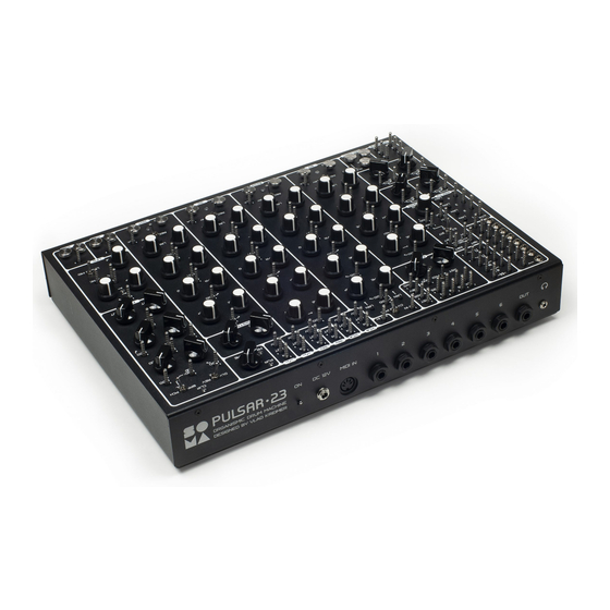
PULSAR•23 USER MANUAL Pulsar-23 is a complex device with many non-obvious functions and capabilities. To unleash its full potential, it is strongly recommended to read these instructions. GENERAL OVERVIEW Pulsar-23 is a multi-functional analog synthesizer and generator of complex rhythmic patterns. The Pulsar consists of 23 different modules, including four flexible sound generators with completely different structures, four envelope generators, four looper-recorders, a clock generator with dividers, a controlled chaos generator, an LFO, a two-channel CV-controlled... - Page 3 USER MANUAL PULSAR•23 You can connect the inputs and outputs of the Pulsar in any combination, without worrying that something will be damaged or done “incorrectly”. At the same time, due to the smart organization of the input and output impedance of the connection points, several signals connected together will be automatically mixed, and the points that can work as input and output (for example, triggering envelope generators) will figure out on their own what is connected to them and start to either receive the signal, or send it, or they will begin mutual...
- Page 4 PULSAR•23 USER MANUAL • You can carry out a lot of experiments by connecting alligator clips to various radio com- ponents, parts of electronic circuits (for example, an old radio), touch plates and even take two forks with connected alligator clips, plug them into a cucumber and listen to how it sounds in the snare drum synthesis chain:).
- Page 5 USER MANUAL PULSAR•23 MIDI The Pulsar has significant capabilities to be controlled via MIDI. MIDI controls have: • Dynamic trigger of all four synthesis modules, taking into account velocity. • The BASS module recognizes pitch bender (the range is +/- 12 semitones) and portamento (CC05).
- Page 6 PULSAR•23 USER MANUAL BASS module will be sent to the output of the first channel of the converter. The CV on this output will be proportional to the note number that is currently played by the BASS module. This function is very useful if, for example, you want the cutoff frequency of the filter to follow the pitch of the note being played.
-
Page 7: Main Modules
USER MANUAL PULSAR•23 MAIN MODULES MASTER CLOCK GENERATOR The basic structure of the Pulsar begins with a master clock gener- ator. When creating a patch, you can make the source of the clock something else and even have several sources at the same time. The clock generator sets the tempo of your rhythmic pattern, as well as the looper/recorder's loop length, which is four measures in four quarters or 128 ticks of the clock. - Page 8 PULSAR•23 USER MANUAL You can connect several outputs of the divider together. The signals will automatical- ly be summed and you will get a complex rhythmic pattern based on this sum. You can use the signal from the outputs of the divider to create the sound of a met- ronome.
- Page 9 USER MANUAL PULSAR•23 a sequencer and an editor based on a personal computer. Therefore, if you need precise control over each beat, we suggest using a computer sequencer (Cubase, Ableton, Protools etc.) connected to the Pulsar via the MIDI interface. Rather, the capabilities of LR are con- centrated on high quality and making live performances more convenient.
- Page 10 PULSAR•23 USER MANUAL DEL sensors — Erase notes from LR loops. If the REC PLAY switch is in the REC position, the DEL sensor deletes notes from the cor- responding loop. If the REC PLAY switch is in the PLAY position, the DEL sensor will mute the recorded notes without changing the contents of the loop.
- Page 11 USER MANUAL PULSAR•23 BLOCK REC.CONT ( RECORDER CONTROL ) This is the looper/recorder control unit. It consists of three multi-function sensors: L, M, BANK, L M sensors — allow you to set the velocity of recorded or played notes. L (low) — lowest velocity. M (middle) —...
- Page 12 PULSAR•23 USER MANUAL AR ENVELOPE GENERATORS OF SYNTHESIS MODULES All synthesis modules (BD, BASS, SD, HHT) have the same envelope generators with two control parameters — Attack (ATT) and Release (REL). The input of the generator is connected to the output of the looper/recorder, the output of the MIDI converter and the TRIG pin.
- Page 13 USER MANUAL PULSAR•23 BD ( BASS DRUM ) SYNTHESIS MODULE Designed for synthesizing the sound of a bass drum. Like other synthesis modules, it can be used to generate a fairly wide range of sounds. It should be noted that all synthesis modules have a different structure and that their sound palettes do not intersect for this reason.
- Page 14 PULSAR•23 USER MANUAL BASS SYNTHESIS MODULE The BASS synthesis module is a powerful monophonic synthesizer with two modes of operation — classic monophonic synthesis and percussion synthesis of the author’s architecture. This allows you to create a wide range of sounds, such as bass, lead, various types of low-frequency and high-frequency percussion, and sound effects.
- Page 15 USER MANUAL PULSAR•23 AMT (amount) knob — determines depth of modulation by the signal received on the MOD pin. LPF FR (low-pass filter frequency) knob — controls the cutoff frequency of the reso- nant low-pass filter. MOD pin associated with the LPF FR knob: CV control of the filter cutoff frequency. LPF Q knob —...
- Page 16 PULSAR•23 USER MANUAL SD ( SNARE DRUM AND CLAP ) SYNTHESIS MODULE The SD synthesis module is focused on producing the sound of a snare drum and a clap, while remaining, like all Pulsar sound modules, flexible enough to synthesize a wide palette of sounds that goes far beyond the classical snare drum.
- Page 17 USER MANUAL PULSAR•23 HHT ( HI-HAT ) SYNTHESIS MODULE A module designed to synthesize the sound of a hi-hat, cymbal or shaker. TUNE knob — adjusts the spectrum of the noise generator. MOD (near the TUNE knob) pin — CV input controlling the noise spectrum.
- Page 18 PULSAR•23 USER MANUAL SHAOS PSEUDO-RANDOM GENERATOR This is a generator of complex pseudo-random signals of the author’s de- sign, built on the basis of shift registers. Hence the name SHIFT + CHAOS = SHAOS. It consists of a clock generator, a shift register with a feedback circuit generating a pseudo-random sequence, along with a sample and hold unit that allows sampling from a pseudo-random sequence, synchronized to an external signal.
- Page 19 USER MANUAL PULSAR•23 All SHAOS outputs are shifted relative to each other and produce different se- quences. If you want SHAOS to work in sync with the master clock, connect the CLK input to the desired output of the master clock divider array. If a signal with a frequency that is not related to the internal SHAOS clock, for exam- ple from the LFO generator, is fed to the S/H input, the length of the pseudo-random sequence will increase significantly, theoretically to infinity.
- Page 20 PULSAR•23 USER MANUAL FX EFFECT PROCESSOR Pulsar contains a two-channel effects processor. The first chan- nel is different types of delay, the second is reverb. FX has three operating modes: BPF (band-pass filter) – Channel 1 is a 1-tap delay with an ad- justable band-pass filter.
- Page 21 USER MANUAL PULSAR•23 TUNE knob — In BPF mode, it adjusts the band pass filter. In DBL mode, it sets the delay time of the second delay line. In PCH mode, it adjusts the pitch interval of the pitch shifter. MOD pin associated with the TUNE knob —...
- Page 22 PULSAR•23 USER MANUAL FREQ (frequency) knob — sets the frequency of the LFO (low frequency oscillator). MOD pin — CV input for controlling the frequency of the LFO. AMT knob — determines the level of influence of the MOD CV on the LFO frequency.
-
Page 23: Additional Modules
USER MANUAL PULSAR•23 ADDITIONAL MODULES ATTENUATORS Pulsar contains four assignable attenuators. They are necessary if you need to reduce or control the level of any audio or CV signal. The right contact is the input, the left contact (wire with an arrow) is the output. Using assign- able attenuators instead of placing a special attenuator near each CV input allowed us to save a huge amount of space on the Pulsar panel, as well as greatly reduce the price. - Page 24 PULSAR•23 USER MANUAL INDIVIDUAL COMPONENTS AND IMPULS CONVERTERS diode is a single radio component, useful for atomic control of signals and circuit bending. You can modulate the velocity of a trigger output of the looper/recorder with the LFO signal. To do this, connect the left contact of the diode (anode) to the TRIG output, and the right contact of the diode (cathode) to the triangle LFO output.
- Page 25 USER MANUAL PULSAR•23 EURORACK - PIN ADAPTER Pulsar has eight adapters for connecting mini-jacks used in Eurorack to the pins designed to connect the alligator clips. If you need more connections with Eurorack — just attach the alligator clip to the mini-jack TIP. At least one of the connections between Pulsar and Eurorack modules must be made through the adapter in order to ensure the connection of the ground of the devices.
- Page 26 PULSAR•23 USER MANUAL AUXILIARY INPUT TO THE MAIN MIX BUS MIX IN pin is an audio input for signals that should be added to the main mix. To create a metronome, connect the output of the clock divider of the desired time signature (usually 4 or 2) to the attenuator input, and connect the attenuator output to the MIX IN.
- Page 27 USER MANUAL PULSAR•23 CONTROLLED SWITCHES There are two voltage-controlled switches. They can be used for control and au- dio signals. Applying a voltage of more than +5 volts to the CV pin will turn the switch on. IN pin — switch input. OUT pin —...
-
Page 28: Rear Panel
PULSAR•23 USER MANUAL REAR PANEL Power switch. DC IN. 12 volts, 0.3 amperes, plus in the center. Only a well-stabilized power supply must be used! If the supplied PSU is out of order, we recommend a modern switching mode power supply with a wide input AC range. They have excellent stabilization. MIDI IN (5-pin DIN). -
Page 29: Specifications
USER MANUAL PULSAR•23 SPECIFICATIONS The range of input and output CV and audio signals ....0 to + 10V (Pulsar inputs are protected against overloads and can receive signals in the range of -20 + 20 volts for a long time without problems) Main output voltage swing . - Page 30 PULSAR•23 USER MANUAL ABBREVIATIONS AND SHORTENINGS +10V — DC 10 volt AMT — amount ATT — attack BD — bass drum CLK — clock DEL — delete DIR — direct DLY — delay ENV — envelope FB — feedback FR — frequency FREQ —...
- Page 31 USER MANUAL PULSAR•23 PULSAR•23 TEAM: Adam Brewczynski — EU commercial department. Anastasia Azartsova — top and rear panel design. Andrzej Slowik — EU production management and control. Arseniy Vasylenko — web administration. Dariusz Kolerski — EU commercial department. Evgeny Aleynik — lawyer consulting. Grigory Ryazanov —...
- Page 32 Manual version 1.0 09/2019. Made in Russia...
Need help?
Do you have a question about the Pulsar 23 and is the answer not in the manual?
Questions and answers