
Related Manuals for Devantech dS3484


Summary of Contents for Devantech dS3484
- Page 1 User Manual v3.01 dS3484 dS3484 User Manual Version 3.01 Copyright © 2016-2018, Devantech Ltd. www.robot-electronics.co.uk All rights reserved.
-
Page 2: Table Of Contents
User Manual v3.01 Table of Contents Documentation history....................3 A quick look........................4 Introduction........................5 Getting started.......................6 Locating the IP Address......................7 Configuring the dS3484....................9 Status page.........................10 Network page........................11 TCP/IP page.........................12 Webpage security.........................14 Configuring relays.........................16 Relay automation........................17 Naming I/O's........................20 Connecting I/O to Virtual Relays................20 Email notifications.........................21... -
Page 3: Documentation History
Application update Added ModBus function 15, Write Multiple Coils. Increased to 32 relays. On dS3484, relays 5-32 are virtual relays. Added CRC calculation to string arrays. Added Modbus gateway to connect to downstream Modbus RTU modules. Added settings for Modbus UID and downstream baud rate & parity. -
Page 4: A Quick Look
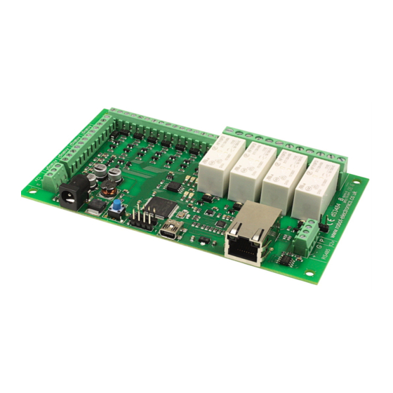
User Manual v3.01 A quick look Ethernet connected module, 10/100Mb auto negotiated. Relays – 4 x 16Amp 250Vac C/O. I/O – 8 x digital I/O's NPN output, Volt free input. 4 x 10-bit analogue input Power – 12VDC 1Amp supply required. 2.1mm center positive. -
Page 5: Introduction
Each relay has both normally open (NO) and normally closed (NC) as well as the common available on three terminals. In addition to the relays, the dS3484 has 8 digital I/O channels and 4 x 10-bit analogue input channels (0v-3.3v input range). -
Page 6: Getting Started
User Manual v3.01 Getting started Start by plugging in the Ethernet cable to connect the module to your network, and the 12v jack plug from your adapter. Switch on and the first thing you will note is that the blue LED will flash 3 times. -
Page 7: Locating The Ip Address
Alternatively, you can find the IP address of the module by checking your DHCP server. If you have a DHCP server on your network (your router is normally the DHCP server) then the dS3484 will get its IP address from that. Log on to your router and navigate to the LAN client list. - Page 8 LAN. DevantechModuleFinder.jar If you do not have a DHCP server the dS3484 will use a default IP address of 192.168.0.123 so make sure your PC is on the same subnet of 255.255.255.0 and its IP address is 192.168.0.xxx...
-
Page 9: Configuring The Ds3484
User Manual v3.01 Configuring the dS3484 There are a set of configuration pages to get the dS3484 operating as you want it. These pages are all _configx.htm, (that's a leading underscore character). _config.htm _config2.htm Anything that starts with _config is considered a special name for configuration pages and can only be seen if you have the the USB cable plugged in and connected to your PC. -
Page 10: Status Page
User Manual v3.01 Status page You should now see the following page: This status page shows you the system and application firmware revisions as well as the supplied voltage to the board and its internal temperature. If you hover your mouse cursor over the menu buttons on the left, the help panel will give you an overview of each one. -
Page 11: Network Page
User Manual v3.01 Network page Notice that everything below the Host Name is greyed out and can't be changed. This is because the “Enable DHCP” box is checked and all the greyed out fields are supplied by the DHCP server. -
Page 12: Tcp/Ip Page
User Manual v3.01 TCP/IP page The TCP/IP tab allows you to select one of three command sets to control the module. These are independent of, and separate to the HTML webpage control. Clicking on one of the four check boxes will select that command set. Only one command set may be selected. - Page 13 When selecting the Modbus commands, an additional set of configuration boxes are available. These allow you to select the UID, normally you will leave this at the default of 1. The dS3484 will respond to commands on this UID. If you send any other UID it will be treated as the address of a Modbus module connected to the RS485 port.
-
Page 14: Webpage Security
User Manual v3.01 Webpage security Allows you to prevent unauthorised personnel from accessing the application webpage or using it to control the module. Leaving the Security Password blank will disable it and allow everyone to access the application page to control the module. - Page 15 User Manual v3.01 You will see something like this: The password is now loaded on your browser. Do the same for any further browsers you want to enable. When you have done uncheck the “Enable _pw.htm” box to prevent anyone else from loading the password.
-
Page 16: Configuring Relays
User Manual v3.01 Configuring relays The next tab allows you to set the names of the 32 relays that will be displayed on the application page. Use the Relay No. box to select the relay to configure. There are 32 relays available. Relays 1- 4 are the physical relays on the module. -
Page 17: Relay Automation
User Manual v3.01 Relay automation There are a set of control boxes that provide for autonomous relay operation. If you just want to control the relays from the webpage or using one of the TCP/IP modes, then leave these boxes blank. - Page 18 User Manual v3.01 Here's a very simple example: Enter R2 into the Relay 1 Pulse/Follow box. This will make relay 1 copy whatever you do to Relay 2. Try it! Now change it to !R1. The exclamation mark is read as “Not R1”. Now relay 1 will always be the opposite of relay 2.
- Page 19 User Manual v3.01 Set Reset & Toggle boxes When used, these three controls contain boolean equations. The “Set Relay” box will set the relay when the boolean equation becomes true. The other two boxes reset and toggle the relay when the boolean equation become true.
-
Page 20: Naming I/O's
User Manual v3.01 Naming I/O's The I/O Names tab is used to assign meaningful names to the I/O terminals. As with relay names these may be up to 20 characters long, but do check it looks ok on a mobile device or whatever you are using to control the module. -
Page 21: Email Notifications
User Manual v3.01 Email notifications The final configuration tab is the Email tab for sending secure, AES encrypted email notifications from the module. Up to eight (8) email notifications may be set up, selected with the Email No. box. -
Page 22: Peer To Peer
User Manual v3.01 Peer to Peer This tab allows you to configure events on this module to control relays on another. Up to eight (8) Peer to Peer events may be set up, selected with the P2P No. box. -
Page 23: Schedules
User Manual v3.01 Schedules The scheduler can schedule regular events. These can be once or twice daily with the two start and stop times and can happen on any selected weekdays. The Schedule No. is one of eight schedules that can be set up, selected with the Schedule No. - Page 24 User Manual v3.01 The timezone allows you to set the time for your location. For example; GMT leave this at 0. CET set this to 1. PST set this to -8 IST set this to 5:30 Daylight saving time may be checked if required. It advances the time by 1 hour between the last Sunday in March and the last Sunday in October.
-
Page 25: Counter/Timers
User Manual v3.01 Counter/Timers Count input pulses or time events. There are a total of eight counter/timers available, selected with the Counter No. box. . Each counter can count at a maximum speed of 20Hz (20 counts per second). - Page 26 User Manual v3.01 Reset Input This input will reset the counter value to zero. If the capture Input has been left blank then it will store the current counter value in the capture register before resetting it to zero. You may use an input such as D3 or you can use the counter value itself.
- Page 27 User Manual v3.01 The internal time base, T1 is derived from the crystal on the module. It’s accurate but will drift over time so that the capture event may not happen “on the hour”. Even if you started it on the hour is will drift out by a few seconds a day.
-
Page 28: The Application Page
User Manual v3.01 The application page The last tab in the configuration pages takes you directly to the application page so you can quickly see the results of your configuration changes. The I/O indicators show grey when the I/O is inactive. -
Page 29: Application Page Security
User Manual v3.01 Application page security The configuration pages (any page name starting with _config) are only served when the USB port is connected. If the USB port is unplugged then no configuration pages are served. Instead, you will be served a page saying “You do not have permission to view this page.”... -
Page 30: Accessing Your Webpage From The Internet
User Manual v3.01 Accessing your webpage from the internet Now you have your webpage up and running on your local network, for example 192.168.0.150, and you can access the webpage and control the module. You just go to 192.168.0.150/index.htm, and the page is there. -
Page 31: Boolean Equations
User Manual v3.01 Boolean equations Boolean equations are used in a number of places in the configuration screens. They are used for relay automation, triggering emails and peer to peer events and the count, capture and reset for the counter/timers. - Page 32 User Manual v3.01 To demonstrate a real world example, take the analog example above where we compared A1 with 1000 to operate R2. Whilst this would work its a not a good solution as the relay would jitter badly when A1 was hovering between 999 and 1000. What we need is some hysteresis.
-
Page 33: Tcp/Ip Command Sets
User Manual v3.01 TCP/IP command sets There are four TCP/IP command sets on four selectable check boxes, of which one or none may be selected on the TCP/IP config tab. These are ASCII, Modbus, Binary and Binary with AES256 encryption. - Page 34 User Manual v3.01 ASCII commands are all two character commands and are not case sensitive. Type ST followed by the return key. This is the STatus command. You will see: Valid commands are: STatus request SR [Relay number] [on/off] {Pulse time in mS}...
- Page 35 User Manual v3.01 Typical PuTTY session. Copyright © 2016-2018, Devantech Ltd. www.robot-electronics.co.uk All rights reserved.
-
Page 36: Binary Command Set
Get Counters 0x30 (decimal 48) Get Status (1 byte command, returning 8 bytes) This command returns 8 bytes of status data Module ID This will be 30 (0x1E) for the dS3484 System Firmware Major 2 for example System Firmware Minor... - Page 37 User Manual v3.01 0x32 0x04 0x01 Set Output (3 byte command, returning 1 byte) This command turns an output on or off and returns an ACK/NACK byte. ACK=0, NACK=non- zero (actually the unknown I/O port number). All I/O's which need to be inputs should have the output turned off. When turned on the NPN transistor can sink up to 100mA.
-
Page 38: Aes Binary Command Set
User Manual v3.01 Binary Command Set – continued. 0x35 Get Analogue inputs (1 byte command returning 8 bytes) This returns all 4 analogue inputs. 8 bytes are returned, 2 for each analogue input. Byte 1 byte 2 for example:... - Page 39 User Manual v3.01 packet. For example when you send a Get Status command (0x30) you will get a 16 byte block returned. The first 8 bytes (0-7) will be as defined for the binary commands. Bytes 8-11 are unused.
-
Page 40: Modbus Commands
User Manual v3.01 Modbus commands The modbus command set accepts a subset of the standard Modbus-TCP frames as defined in Modbus protocol Specification MODBUS Messaging on TCP/IP Implementation Guide V1.0b Functions 1, 4, 5 & 15 are supported along with error codes 1, 2 & 3 should they occur. -
Page 41: Function 05 (0X05) Write Single Coil
User Manual v3.01 Function 05 (0x05) Write Single Coil This function is used to write to a single coil (relay or I/O). Coils 1-8 are the relays 1-8. Coils 9-15 are the I/O's 1-7 remapped to coils 9-15. -
Page 42: Loading The Application Firmware
In this order: 1. Start from this position: a. dScript Editor closed down. b. dS3484 not connected or powered. 2. Power-up the dS3484. 3. Hold down the reset button for a couple of seconds until the red LED comes on. This indicates the module is in boot-loader mode. - Page 43 User Manual v3.01 folder and install the driver from there. 5. Run the dScript editor. Look in Help About and check you have the latest version of → dScript. If you have an earlier version you should uninstall it and install the new version from the installation folder, then start these instructions from the beginning.
-
Page 44: Erasing Old Configuration Settings
Load up the app-dS3484-v3.01 application in the editor, but before you upload it to the dS3484 you need to make a small change. Locate the label "main" (click the word in the right panel is quickest). Just below this is a commented out line "gosub init". -
Page 45: Ds3484 Hardware
User Manual v3.01 dS3484 hardware The dS3484 provides four (4) volt free contact relay outputs with a current rating of up to 16Amp each, 8 digital I/O's which can be an NPN transistor output or accept a volt free input (from relay or switch contacts, etc). -
Page 46: Led Indication
The “FlashingLeds” example provides a colourful display showing how to use them. Power supply The dS3484 requires a 12v DC supply capable of supplying a minimum of 1A. This is most easily provided by a low cost mains adapter. A suitable universal adapter is available on our website and may be ordered along with the modules. -
Page 47: Power Relays
The relay coil is powered by the 12vdc incoming supply on user command. Coil Relay in passive state Coil Relay in powered state A full datasheet for the relays used on the dS3484 is here: HF115FD datasheet Copyright © 2016-2018, Devantech Ltd. www.robot-electronics.co.uk... -
Page 48: Digital Io
Our Ethernet modules could potentially have many types of outputs. For example the ETH008 only has one type - Relays. The dS3484 has both Relay outputs and NPN Open Collector Transistor outputs. Activating a relay means turning the relay on. Likewise activating an output means turning the transistor on. -
Page 49: Connection Examples
User Manual v3.01 Connection Examples Example input - connecting a switch Connecting a simple switch could not be easier, just wire the switch between a pin (P) and ground (G). When the switch closes the input will become active. -
Page 50: Analogue Inputs
User Manual v3.01 Representative Digital I/O Schematic Analogue inputs Four independent analogue input channels are provided for sampling voltages up to 3.3V. Each channel is also filtered with a 10k resistor and a 100n capacitor to stabilise high frequency jitter, there is also a pull down resistor so the port will read around 0 when nothing is connected. - Page 51 User Manual v3.01 Representative Analogue Schematic Copyright © 2016-2018, Devantech Ltd. www.robot-electronics.co.uk All rights reserved.
-
Page 52: Serial Port Connections
User Manual v3.01 Serial Port Connections TTL serial ports. The dS3484 has two serial port headers. Pin 1 is marked on the PCB. Tx and Rx operates at 3.3v levels, however the Rx input is 5v tolerant. Most 5v TTL level serial ports will accept a full 3.3v input... -
Page 53: Ds3484 Dimensions
User Manual v3.01 dS3484 dimensions Copyright © 2016-2018, Devantech Ltd. www.robot-electronics.co.uk All rights reserved. -
Page 54: Notes
User Manual v3.01 Notes Copyright © 2016-2018, Devantech Ltd. www.robot-electronics.co.uk All rights reserved.
Need help?
Do you have a question about the dS3484 and is the answer not in the manual?
Questions and answers