
Related Manuals for Devantech ESP32LR20


Summary of Contents for Devantech ESP32LR20
- Page 1 ESP32LR20 User Manual v1.02 ESP32LR20 User Manual Version 1.02 Copyright © 2018, Devantech Ltd. www.robot-electronics.co.uk All rights reserved.
-
Page 2: Table Of Contents
ESP32LR20 User Manual v1.02 Table of Contents Overview..............................3 Control Protocols............................3 WiFi................................3 Configuration.............................3 USB Configuration Commands.........................4 ST Status. Return the system status.......................4 RB ReBoot............................5 IP Sets the modules IP address......................5 SB Sets the SuBnet mask........................5 GW Sets the GateWay address......................5 PD Sets the Primary DNS........................6 SD Sets the Secondary DNS.........................6... -
Page 3: Overview
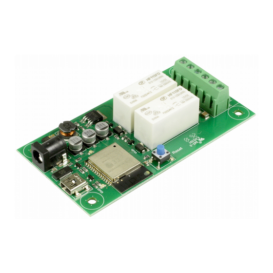
4. A built in webpage WiFi The ESP32LR20 connects via WiFi to your network. Therefore it must be located in a position where it gets a good WiFi signal. The module should not be enclosed in a metal box/cabinet as this will shield the WiFi signal. -
Page 4: Usb Configuration Commands
ASCII TCP Port: 17123 RSSI: -72 MQTT Server: 192.168.0.115 MQTT Port: 1883 MQTT ID: ESP32LR20 Relay1 Topic: R1Topic Relay2 Topic: R2Topic When the IP address is set to 0.0.0.0 this means that the IP address is being provided by your networks DHCP server. In that case the assigned IP address is also provided, as above. -
Page 5: Rb Reboot
ESP32LR20 User Manual v1.02 RB ReBoot. This will restart the module. It may produce a lot of random characters as the ESP32’s boot logging runs at a different baud rate. If it succeeds in connecting to your network it will report the IP address. -
Page 6: Pd Sets The Primary Dns
OK. Saved Secondary DNS: 8.8.4.4 SS This sets the SSID. The SSID is the public name of your WIFI network Enter your WIFI’s SSID here. SS “Devantech” OK. Saved SSID: Devantech PW Sets your networks WIFI password. PW "K]~kCZUV*UGA6SG~" OK. Saved Password: K]~kCZUV*UGA6SG~ PA Sets the TCP/IP port number for the ASCII commands. -
Page 7: Ms Sets The Mqtt Broker Address
ESP32LR20 User Manual v1.02 MS Sets the MQTT broker address MS “192.168.0.121” OK. Saved MQTT Server: 192.168.0.121 MD Sets the MQTT ID for this module MS “UniqueModuleName” OK. Saved MQTT ID: UniqueModuleName MP Sets the MQTT broker’s port. Normally, this should be set to 1883. -
Page 8: Tcp/Ip Commands
ESP32LR20 User Manual v1.02 TCP/IP Commands. The ESP32LR20 has a built in TCP/IP command set which allows you to control the module remotely. All commands are sent using plain ASCII text. PuTTY is a good cross platform terminal program to use for testing. -
Page 9: Html Commands
ESP32LR20 User Manual v1.02 HTML Commands. There are a set of HTML commands that can be used to control the module. ?Rly2=1 This will turn on relay 2 ?Rly2=0 This will turn off relay 2 ?Rly2=2 This will toggle relay 2 to the opposite state. -
Page 10: Webpage
ESP32LR20 User Manual v1.02 Webpage The built in webpage can be used as a remote app to monitor and control the relays. Your can access the page as a default with just the IP address or by specifying index.htm. The webpage contains the Javascript to send an HTML toggle command, as described in the previous section. -
Page 11: Schematics
ESP32LR20 User Manual v1.02 Schematics Note. The CPU schematic is the same for the ESP32LR20, ESP32LR42 and ESP32LR88. Relays 3-8 and Inputs 1-8 are not available on the ESP32LR20 Copyright © 2018, Devantech Ltd. www.robot-electronics.co.uk All rights reserved. -
Page 12: Power Supply
ESP32LR20 User Manual v1.02 Power Supply Copyright © 2018, Devantech Ltd. www.robot-electronics.co.uk All rights reserved. -
Page 13: Relay Outputs
ESP32LR20 User Manual v1.02 Relay Outputs 1 of 2 identical circuits shown The relays are capable of switching up to 16 Amps at 24vdc or 230vac. A data sheet of the relay can be found here. Only the normally open (N/O) contact has the snubber circuitry. -
Page 14: Pcb Dimensions
ESP32LR20 User Manual v1.02 PCB dimensions Copyright © 2018, Devantech Ltd. www.robot-electronics.co.uk All rights reserved. -
Page 15: Notes
ESP32LR20 User Manual v1.02 Notes Copyright © 2018, Devantech Ltd. www.robot-electronics.co.uk All rights reserved.
Need help?
Do you have a question about the ESP32LR20 and is the answer not in the manual?
Questions and answers