
Related Manuals for Devantech dS378


Summary of Contents for Devantech dS378
- Page 1 User Manual v2.19 dS378 dS378 User Manual Version 2.19 Copyright © 2016-2017, Devantech Ltd. www.robot-electronics.co.uk All rights reserved.
-
Page 2: Table Of Contents
User Manual v2.19 Table of Contents Documentation history....................3 A quick look........................4 Introduction........................5 Getting started.......................6 Configuring the dS378....................8 Status page.......................9 Network page......................10 TCP/IP page......................11 Webpage security.....................12 Naming relays......................14 Relay automation.....................15 Naming I/O's......................16 Email notifications....................17 Peer to Peer......................18 Schedules........................19 Counter/Timers......................21 The application page.....................24... -
Page 3: Documentation History
User Manual v2.19 Documentation history V2.18 First release of separate dS378 manual V2.19 Added new features: Peer to Peer Use events to control relays on another dSxxxx module. Schedules Create regular timed events Counters Count input transitions or seconds Copyright ©... -
Page 4: A Quick Look
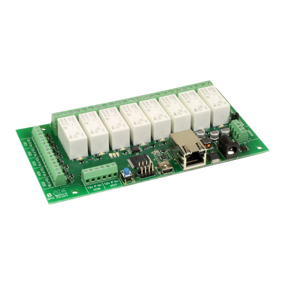
User Manual v2.19 A quick look Ethernet connected module, 10/100Mb auto negotiated. Relays – 8 x 16Amp 250Vac C/O. I/O – 7 x flexible I/O's NPN output, Volt free input or 10-bit analogue input. Power – 12VDC 1Amp supply required. 2.1mm center positive. -
Page 5: Introduction
Each relay has both normally open (NO) and normally closed (NC) as well as the common available on three terminals. In addition to the relays, the dS378 has 7 flexible I/O channels which may be individually configured to be: 1. -
Page 6: Getting Started
User Manual v2.19 Getting started Start by plugging in the Ethernet cable to connect the module to your network, and the 12v jack plug from your adapter. Switch on and the first thing you will note is that the blue LED will flash 3 times. - Page 7 If you are not using a windows PC then you will need to find the IP address of the module. If you have a DHCP server on your network (your router is normally the DHCP server) then the dS378 will get its IP address from that. Log on to your router and navigate to the LAN client list.
-
Page 8: Configuring The Ds378
User Manual v2.19 If you do not have a DHCP server the dS378 will use a default IP address of 192.168.0.123 so make sure your PC is on the same subnet of 255.255.255.0 and its IP address is 192.168.0.xxx Configuring the dS378 There are a set of configuration pages to get the dS378 operating as you want it. -
Page 9: Status Page
User Manual v2.19 Status page You should now see the following page: This status page shows you the system and application firmware revisions as well as the supplied voltage to the board and its internal temperature. If you hover your mouse cursor over the menu buttons on the left, the help panel will give you an overview of each one. -
Page 10: Network Page
User Manual v2.19 Network page Notice that everything below the Host Name is greyed out and can't be changed. This is because the “Enable DHCP” box is checked and all the greyed out fields are supplied by the DHCP server. -
Page 11: Tcp/Ip Page
User Manual v2.19 TCP/IP page The TCP/IP tab allows you to select one of three command sets to control the module. These are independent of, and separate to the HTML webpage control. Clicking on one of the four check boxes will select that command set. Only one command set may be selected. -
Page 12: Webpage Security
User Manual v2.19 Webpage security Allows you to prevent unauthorised personnel from accessing the application webpage or using it to control the module. Leaving the Security Password blank will disable it and allow everyone to access the application page to control the module. - Page 13 User Manual v2.19 You will see something like this: The password is now loaded on your browser. Do the same for any further browsers you want to enable. When you have done uncheck the “Enable _pw.htm” box to prevent anyone else from loading the password.
-
Page 14: Naming Relays
User Manual v2.19 Naming relays The next tab allows you to set the names of the 8 relays that will be displayed on the application page. Names may be up to 20 characters long, but keep them shorter if you want to use a phone as the controller. -
Page 15: Relay Automation
User Manual v2.19 Relay automation The box to the right of the relay name box is used to give a little automation to the relay. Leave this blank (or zero) for normal operation, that is just toggling the relay on/off from the button on the application page. -
Page 16: Naming I/O's
User Manual v2.19 Naming I/O's The I/O Names tab is used to assign meaningful names to the I/O terminals. As with relay names these may be up to 20 characters long, but do check it looks ok on a mobile device or whatever you are using to control the module. -
Page 17: Email Notifications
User Manual v2.19 Email notifications The final configuration tab is the Email tab for sending secure, AES encrypted email notifications from the module. Up to eight (8) email notifications may be set up, selected by the eight radio buttons. -
Page 18: Peer To Peer
User Manual v2.19 Peer to Peer This tab allows you to configure events on this module to control relays on another. Up to eight (8) Peer to Peer events may be set up, selected by the eight radio buttons. -
Page 19: Schedules
User Manual v2.19 Schedules The scheduler can schedule regular events. These can be once or twice daily with the two start and stop times and can happen on any selected weekdays. The Schedule No. is one of eight schedules that can be set up. These are selected with the eight radio buttons at the bottom of the screen. - Page 20 User Manual v2.19 The timezone allows you to set the time for your location. For example; GMT leave this at 0. CET set this to 1. PST set this to -8 IST set this to 5:30 Daylight saving time may be checked if required. It advances the time by 1 hour between the last Sunday in March and the last Sunday in October.
-
Page 21: Counter/Timers
User Manual v2.19 Counter/Timers Count input pulses or time events. There are a total of eight counter/timers available, selected with the 8 radio buttons. Each counter can count at a maximum speed of 20Hz (20 counts per second). - Page 22 User Manual v2.19 Counters, Timers and Schedules can be combined. As an example lets assume we want to count the pulses on input 2. We need to know the number of pules per hour coming in. First we need a 1 hour time base, we’ll use counter/timer 1 for this.
- Page 23 User Manual v2.19 over time so that the capture event may not happen “on the hour”. Even if you started it on the hour is will drift out by a few seconds a day. So as a final refinement we will synchronize our time base with the real time derived from a schedule.
-
Page 24: The Application Page
User Manual v2.19 The application page The last tab in the configuration pages takes you directly to the application page so you can quickly see the results of your configuration changes. The I/O indicators show grey when the I/O is inactive. When an active input is applied they show green. -
Page 25: Application Page Security
User Manual v2.19 Application page security The configuration pages (any page name starting with _config) are only served when the USB port is connected. If the USB port is unplugged then no configuration pages are served. Instead, you will be served a page saying “You do not have permission to view this page.”... -
Page 26: Accessing Your Webpage From The Internet
User Manual v2.19 Accessing your webpage from the internet Now you have your webpage up and running on your local network, for example 192.168.0.150, and you can access the webpage and control the module. You just go to 192.168.0.150/index.htm, and the page is there. -
Page 27: Boolean Equations
User Manual v2.19 Boolean equations Both relay automation and email triggering use the boolean equation solver. The three types that can be used in boolean equations are: 1. Relays, R1 – R8 2. Digital I/O's, D1 – D7 3. - Page 28 User Manual v2.19 To demonstrate a real world example, take the analog example above where we compared A1 with 1000 to operate R2. Whilst this would work its a not a good solution as the relay would jitter badly when A1 was hovering between 999 and 1000. What we need is some hysteresis.
-
Page 29: Tcp/Ip Command Sets
User Manual v2.19 TCP/IP command sets There are four TCP/IP command sets on four selectable check boxes, of which one or none may be selected on the TCP/IP config tab. These are ASCII, Modbus, Binary and Binary with AES256 encryption. - Page 30 GC 1 Get Counter1 – responds with count, capture values. Note – on the dS378, GI and GA are identical, getting the digital state or analogue value depending on the port configuration in the I/O Types tab. Typical PuTTY session.
-
Page 31: Binary Command Set
Get Counters 0x30 (decimal 48) Get Status (1 byte command, returning 8 bytes) This command returns 8 bytes of status data Module ID This will be 35 (0x23) for the dS378 System Firmware Major 2 for example System Firmware Minor... - Page 32 User Manual v2.19 Binary Command Set – continued. 0x32 0x04 0x01 Set Output (3 byte command, returning 1 byte) This command turns an output on or off and returns an ACK/NACK byte. ACK=0, NACK=non- zero (actually the unknown I/O port number).
-
Page 33: Aes Binary Command Set
User Manual v2.19 Binary Command Set – continued. 0x35 Get Analogue inputs (1 byte command returning 14 bytes) This returns all 7 possible analogue inputs. 14 bytes are returned, 2 for each analogue input. Byte 1 byte 2... - Page 34 User Manual v2.19 To prevent re-play (or Playback) attacks the command packet includes a Nonce. This takes the form of a 32-bit (4 byte) random number in positions 12, 13, 14 & 15 of the 16 byte data packet.
-
Page 35: Modbus Commands
User Manual v2.19 Modbus commands The modbus command set accepts a subset of the standard Modbus-TCP frames as defined in Modbus protocol Specification MODBUS Messaging on TCP/IP Implementation Guide V1.0b Functions 1, 4, & 5 are supported along with error codes 1, 2 & 3 should they occur. -
Page 36: Error Code 1
User Manual v2.19 Error code 1 This error is returned if an unknown or unimplemented function is received. Only functions 1, 4 & 5 are implemented. Error code 2 This error is returned if an illegal address is requested. Addresses greater than 15 for functions 1 &... -
Page 37: Loading The Application Firmware
In this order: 1. Start from this position: a. dScript Editor closed down. b. dS378 not connected or powered. 2. Power-up the dS378. 3. Connect the USB lead to the PC. If windows wants a driver, point it to the USB driver folder and install the driver from there. - Page 38 User Manual v2.19 → 5. Run the dScript editor. Look in Help About and check you have the latest version of dScript. In this case 2.19 If you have an earlier version you should uninstall it and install the new version from the installation folder, then start these instructions from the beginning.
-
Page 39: Ds378 Hardware
User Manual v2.19 dS378 hardware Copyright © 2016-2017, Devantech Ltd. www.robot-electronics.co.uk All rights reserved. -
Page 40: Led Indication
Power supply The dS378 requires a 12v DC supply capable of supplying a minimum of 1A. This is most easily provided by a low cost mains adapter. A suitable universal adapter is available on our website and may be ordered along with the modules. Connection is via the 2.1mm DC jack socket. -
Page 41: Power Relays
The relay coil is powered by the 12vdc incoming supply on user command. Coil Relay in passive state Coil Relay in powered state A full datasheet for the relays used on the dS378 is here: HF115FD datasheet Copyright © 2016-2017, Devantech Ltd. www.robot-electronics.co.uk... -
Page 42: Analogue/Digital Flexible I/O's
User Manual v2.19 Analogue/Digital flexible I/O's The dS378 has seven flexible I/O ports, numbered 1-7, which can be your selection of: 1. Digital open collector output. 2. Digital open collector output with passive pullup to 12v 3. Digital input (0-12v, 2.5v threshold). - Page 43 User Manual v2.19 Representative flexible I/O schematic P1 controls the passive pull-up. It is automatically disabled in analogue modes and set by the option in the digitalport declaration in digital modes. Q1 controls the open collector NPN output. It is set by writing to the port.
-
Page 44: Serial Port Connections
User Manual v2.19 Serial port connections TTL serial port. The dS378 has two serial port headers, 1 and 2 in dScript. Pin 1 is marked on the PCB. Tx and Rx operates at 3.3v levels, however the Rx input is 5v tolerant. Most 5v TTL level serial ports will accept a full 3.3v input... -
Page 45: Ds378 Dimensions
User Manual v2.19 dS378 dimensions Copyright © 2016-2017, Devantech Ltd. www.robot-electronics.co.uk All rights reserved. -
Page 46: Notes
User Manual v2.19 Notes Copyright © 2016-2017, Devantech Ltd. www.robot-electronics.co.uk All rights reserved.
Need help?
Do you have a question about the dS378 and is the answer not in the manual?
Questions and answers