Table of Contents
Advertisement
Quick Links
Advertisement
Table of Contents

Related Manuals for Aventics Marex 3D


Summary of Contents for Aventics Marex 3D
- Page 1 Operating instructions Marex 3D R417003094/11.2018, EN...
-
Page 3: Table Of Contents
AVENTICS | Marex 3D | R417003094–BDL–001–AA Table of Contents Table of Contents About this documentation ..........6 Validity of this documentation..........6 Required and additional documentation ......6 Information presentation ............7 1.3.1 Safety messages ..............7 1.3.2 Symbols ..................8 1.3.3... - Page 4 ............64 6.2.4 Deactiving the heading sensor .......... 65 6.2.5 Adjusting Marex OS for the operation with Marex 3D 66 6.2.6 Disabling the direct command transfer ......67 6.2.7 Marex ECS in combination with Marex 3D ..... 68 6.2.8...
- Page 5 AVENTICS | Marex 3D | R417003094–BDL–001–AA Table of Contents 7.3.2 By movement of control head lever (direct command transfer) ..........82 Activating the thruster mode..........82 7.4.1 Switching the thruster mode off ........83 Maneuvering in the 3D mode..........83 7.5.1 Maneuvering in the Thruster mode ......... 87 7.5.2...
-
Page 6: About This Documentation
Marex OS III and Marex ECS will only be described in this manual if required for the understanding and operation of Marex 3D. Refer to the manuals on Marex OS III and Marex ECS for details on those systems. -
Page 7: Information Presentation
AVENTICS | Marex 3D | R417003094–BDL–001–AA About this documentation Table 1: Required and additional documentation Name Document No. Document type MarexOSII/III: Devices and R419300593 System manual Adjustment MarexOSII/III: Service R419300595 Service manual Manual 3D Tuning R417003097 Software description Joystick Type 531... -
Page 8: Symbols
AVENTICS | Marex 3D | R417003094–BDL–001–AA About this documentation Safety instructions are structured as follows: SIGNAL WORD Type and source of risk Consequences Precautions Warning sign: Draws attention to the risk Signal word: Identifies the hazard level Type and source of hazard: Identifies the type and source of... -
Page 9: Designations
The following designations are used in these operating instructions: Designation Meaning 3D mode Operating mode of Marex 3D in which the joystick controls all ship propulsions. 3D Tuning Aventics software to modify settings in Marex 3D BCS, CMC, Side Thruster types... -
Page 10: Abbreviations
AVENTICS | Marex 3D | R417003094–BDL–001–AA About this documentation Designation Meaning Trolling Clutch operating mode in which the clutch is operated with variable slip. Warming up Engine acceleration with the transmission in neutral position. The following names apply for the commands set via the control head lever for engine speed and transmission direction. -
Page 11: Safety Instructions
Starboard Safety instructions About this chapter All components of the ship remote control Marex 3D have been manufactured in compliance with the generally accepted rules of technology. However, this does not exclude the risk of damage to persons or property if the general safety instructions in this chapter and the safety instructions in this document are not observed. -
Page 12: Improper Use
AVENTICS | Marex 3D | R417003094–BDL–001–AA Safety instructions To operate ships equipped with petrol or gas-fueled engines if all Marex 3D components are installed outside the hazardous area. A separate emergency stop must be provided on every control station. The instructions and warnings referring to the use of the heading mode must be observed, see also chapter 2.6, Product- and technology-related safety... -
Page 13: Qualifications Of Operators
Along with the qualifications in seamanship which are required to command a ship, the operator of the ship remote control Marex 3D must be sufficiently familiar with Marex 3D. Sufficiently familiar includes having read and understood this manual and knowing all important control functions and their operation. -
Page 14: Product- And Technology-Related Safety Messages
AVENTICS | Marex 3D | R417003094–BDL–001–AA Safety instructions If safety devices are taken out of operation in order to work on the product you must make sure that no risk arises for persons or property. Observe the additional documentations. Warranty applies exclusively for the configuration supplied. -
Page 15: Operator's Obligations
The safety of the crew and other waterway users must not be endangered. Parameters in Marex 3D must only be changed by qualified personnel as per chapter 2.4. Appropriate steps must be taken to prevent that control is lost over the ship as a result of erroneous parameter entries (ensure local operation of gearbox, engine, thrusters). -
Page 16: Protective Devices
Protective devices 2.8.1 Emergency stop Marex 3D must only be operated with a separate emergency stop provided on every control station. It is not included in any of the Marex systems. It must be fully operational at all times, especially in case of a remote control failure. Normally, the emergency stop is part of the ship’s safety system. -
Page 17: About This Product
Intended use, on page 11. About this product Performance description Marex 3D is a simple and intuitive tool for easy docking at slow speeds. Its main operating element is a joystick which the operator can rotate and/or push. Marex 3D converts the movement of the joystick into movement of the ship by actuating the available drives in an intelligent way. - Page 18 A software tool is available to adapt the settings of Marex 3D to the ship’s requirements. Individual adjustments can be made for every maneuver. For the protection of electric ON/OFF-...
-
Page 19: Drive Combinations
Product description 4.2.1 System setup and symbols This section shows the standard setups of Marex 3D in combination with Marex OS III and Marex ECS. The figures use the following symbols: Position of the dip switch for the bus terminating resistor in... - Page 20 AVENTICS | Marex 3D | R417003094–BDL–001–AA About this product Number of CAN bus connector Type of connector (male/female) A standard Marex 3D system comprises Joystick Type 531 3D Controller Heading sensor CAN cabling and adapters In applications with Marex OS III, one CAN bus line is connected to the control units of Marex OS III (Cross CAN bus).
- Page 21 AVENTICS | Marex 3D | R417003094–BDL–001–AA About this product 4.2.1.1 Marex OS III - single engine Different setting of terminating resistor: With Marex OS single engine systems, dip switch S2 at the 3D Controller must be set to "on".
- Page 22 AVENTICS | Marex 3D | R417003094–BDL–001–AA About this product 4.2.1.2 Marex OS III - twin engines...
- Page 23 AVENTICS | Marex 3D | R417003094–BDL–001–AA About this product 4.2.1.3 Marex ECS - single engine...
-
Page 24: Control Stations
AVENTICS | Marex 3D | R417003094–BDL–001–AA About this product 4.2.1.4 Marex ECS - twin engines 4.2.2 Control stations Stations from which the ship can be navigated are called control stations. These can be equipped with a joystick, a Marex control head or both. -
Page 25: Keys And Display
6 joysticks can be installed. An identification (ID) which is used for the data bus communication within Marex 3D is assigned to every joystick . The table below gives an overview on the control stations and the IDs of the corresponding joystick. -
Page 26: Component Overview
AVENTICS | Marex 3D | R417003094–BDL–001–AA About this product joystick is moved, the control maintains the heading of the bow if an optional heading sensor is connected. Thruster mode In the thruster mode, the joystick is used to control the thrusters only. -
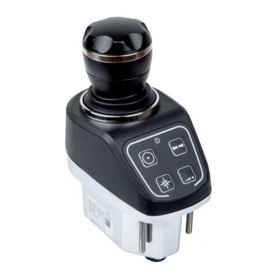
Page 27: Joystick Type 531
9, Accessories, on page 92. 4.3.1 Joystick Type 531 The Joystick Type 531 is the operating element of Marex 3D used to maneuver the ship intuitively at slow speeds. It is designed for panel installation at indoor or outdoor control stations. - Page 28 AVENTICS | Marex 3D | R417003094–BDL–001–AA About this product rotating angle and speed of the ship. The control stick can be moved along two axes. Its travel presets the thrust vector and defines the magnitude and heading of the thrust.
- Page 29 AVENTICS | Marex 3D | R417003094–BDL–001–AA About this product Refer to the assembly instructions of the Joystick Type 531 for further information. See also chapter 1.2, Required and additional documentation, on page 6. 4.3.1.2 Keypad and indicators The Joystick Type 531 provides a keypad for the operation. The...
-
Page 30: 3D Controller
White: The joystick is not ready. Red: The joystick is defect. System error indicator (7) Yellow (Warning) There is an error in the Marex 3D system, but the operation of the joystick can be continued without restriction. Red (Alarm) There is an alarm in the Marex 3D system. The operation of this joystick is no longer possible or possible with restrictions only. - Page 31 AVENTICS | Marex 3D | R417003094–BDL–001–AA About this product thrusters in an intelligent way. As a result, the ship‘s movement follows the setting of the joystick with a high grade of precision. In the heading mode, the data from the heading sensor is included in the vector calculation and used to hold the ship’s...
- Page 32 AVENTICS | Marex 3D | R417003094–BDL–001–AA About this product Fig. 4: Top view of the board without cover Refer to chapter 5.3, Establishing the electrical connections, on page 39 for information on the connections. See also chapter 1.2, Required and additional documentation, on page 6.
- Page 33 In this manual, the settings and parameters which are relevant for commissioning, operating and troubleshooting Marex 3D are explained in the corresponding chapters. Refer to the manual Marex OS II/III, Devices and Adjustments, for further information on the display menues and parameters.
- Page 34 AVENTICS | Marex 3D | R417003094–BDL–001–AA About this product 4.3.2.3 Dip switch elements The electronic board of the 3D Controller is equipped with several dip switches each of which provides 2 switch elements. The dip switches S1, S2 and S7 are used to activate or deactivate the terminating resistors of the CAN and NMEA 2000 bus outputs.
-
Page 35: Heading Sensor
Heading sensor, R419801301 The heading sensor includes a three-axis, electronic compass and supplies Marex 3D with precise data on the ship‘s position. Under dynamic conditions with rough seas, the heading sensor performs with 2° heading accuracy. In static condition, an accuracy of 1°... -
Page 36: Installation
Provide enough space to mount the components professionally. Handle sharp-edged parts with care. Only install Marex 3D components if all plugs are removed and the components are powered off. Protect the power supply against being switched on unintentionally as long as you work on the system. -
Page 37: Mounting The Heading Sensor
AVENTICS | Marex 3D | R417003094–BDL–001–AA Installation lengths. See also chapter 1.2, Required and additional documentation, on page 1.2. Observe project-specific documentation if applicable. Refer to the manual "MarexOSII/III, Devices and adjustments" for information on installing and starting up MarexOS standard components. - Page 38 AVENTICS | Marex 3D | R417003094–BDL–001–AA Installation VHF antenna or Whip antenna Whip antenna Tx MF/HF Rx MF/HF not within INMARSAT beam Loop antenna Radar not within Radar beam > 3m Heading > 2m Sensor > 2m > 5m > 1.5 m >...
-
Page 39: Establishing The Electrical Connections
AVENTICS | Marex 3D | R417003094–BDL–001–AA Installation Establishing the electrical connections 5.3.1 Connecting the 3D Controller 5.3.1.1 Grounding The 3D Controller must be grounded effectively to connect all reference potentials of the distributed equipments. The ground connections have to be as short as possible and with a maximum ground area. - Page 40 AVENTICS | Marex 3D | R417003094–BDL–001–AA Installation Fig. 11: 3D Controller, grounding screw Cable shields must be connected at both ends and over the entire circumference. These connections shall be done preferably through the same housing to which the cable leads.
- Page 41 AVENTICS | Marex 3D | R417003094–BDL–001–AA Installation Shielded cables must be used for CAN bus connections. Openings and connectors which are unused must be covered with protective caps. 5.3.1.2 Applying the cable glands Cable glands must be used to provide a safe and reliable connection.
- Page 42 AVENTICS | Marex 3D | R417003094–BDL–001–AA Installation apply the shield to the cone within the cable gland of the connected devices. Fig. 14: Cable gland Proceed as follows: 1. Strip off the insulation over a sufficient length that allows you to connect the individual wires to the housing.
- Page 43 AVENTICS | Marex 3D | R417003094–BDL–001–AA Installation Fig. 15: Hexagone nut (8) 5.3.1.3 Connecting the power supply After applying the cable glands, connect the cables for the power supply to terminal X5 of the 3D Controller (see fig. 16). Fig. 16: Terminal block X5 for the power supply...
-
Page 44: Connecting Marex Os Iii And Marex Ecs
AVENTICS | Marex 3D | R417003094–BDL–001–AA Installation When using the cables No. R419801568 or R419801522, cut the connector and attach the wires directly to terminals 1 and 4. Only use the option with the dual battery cable, if both voltage sources have the same potential. The negative terminals of both voltage sources must be bridged (common ground). - Page 45 AVENTICS | Marex 3D | R417003094–BDL–001–AA Installation Fig. 18: Connection diagram for Marex OS III with twin engines Fig. 19: Connection diagram for Marex OS III with single engine Different setting of terminating resistor: With Marex OS single engine systems, dip switch S2 at the...
- Page 46 3D Controller. Depending on the setup of your Marex 3D system, it can be required to adjust the settings of the terminating resistors in the 3D Controller.
-
Page 47: Connecting The Joystick
5.3.3 Connecting the Joystick 5.3.3.1 Connectors At the bottom of the joystick, two round M12 connectors are provided for the connection to the Marex 3D controller and other joysticks. Fig. 21: Electrical connectors X11 M12, 5 pins, male Connection for the 3D controller... - Page 48 There is no need to connect a terminating resistor to the Marex 3D controller as one is already included in the device. Fig. 22: CAN bus connection Marex 3D controller to Joystick Type 531 Terminating resistor in the 3D Controller...
-
Page 49: Connecting An Optional Heading Sensor
AVENTICS | Marex 3D | R417003094–BDL–001–AA Installation 5.3.4 Connecting an optional heading sensor Fig. 23: Heading sensor R419801301 Fig. 24: Connection of the heading sensor R419801301 The optional heading sensor is connected to connector X32 at the 3D Controller, using the sensor cable NMEA 2000 R419801829. -
Page 50: Connecting The Thrusters
NMEA2000-bus at connector X32 of the 3D controller. The S-Link gateway is not part of the scope of supply of Aventics. Additionally, an S-Link interface cable is required which must be ordered separately. (See also chapter 9, Accessories on page 92). - Page 51 AVENTICS | Marex 3D | R417003094–BDL–001–AA Installation Contact Aventics at marineservice@aventics.com for further thruster types and questions on the connection. Fig. 26: 3D Controller, terminal blocks...
- Page 52 AVENTICS | Marex 3D | R417003094–BDL–001–AA Installation § ¨ ¥ ¦ £ ¤ ¢ 24V DC -25%/+30% 1, 2, 3 supply voltage 12V DC -20%/+30% 4, 5, 6 terminals for unrestricted 7, 8 terminnals for current measurement for proportional proportional valve: 9, 12 ...
- Page 53 AVENTICS | Marex 3D | R417003094–BDL–001–AA Installation Fig. 28: Terminal connection table...
- Page 54 AVENTICS | Marex 3D | R417003094–BDL–001–AA Installation 5.3.5.1 Connecting ON/OFF-thrusters Fig. 29: Connection of On/Off-thrusters - bow Fig. 30: Connection of On/Off-thrusters - bow and stern...
- Page 55 AVENTICS | Marex 3D | R417003094–BDL–001–AA Installation 5.3.5.2 Connecting Side Power thrusters with S-Link Side-Power thrusters can be controlled using either analog and digital in- and outputs (fig. 27) or a connection to the NMEA2000 bus line. If the 3D Controller is integrated as a participant on the NMEA2000 bus, an S-link gateway is required for the connection.
- Page 56 AVENTICS | Marex 3D | R417003094–BDL–001–AA Installation Fig. 32: Connection of SidePower thrusters via S-Link without a heading sensor 5.3.5.3 Connecting CMC thrusters Fig. 33: Connection of CMC thrusters, bow...
- Page 57 AVENTICS | Marex 3D | R417003094–BDL–001–AA Installation Fig. 34: Connection of CMC thrusters, bow and stern 5.3.5.4 Connecting BCS thrusters Fig. 35: Connection of BCS thrusters, bow...
-
Page 58: Commissioning
Fig. 36: Connection of BCS thrusters, bow and stern The load of digital outputs must not exceed 2A. Commissioning This chapter describes how to start up Marex 3D initially using the standard system configuration supplied on delivery. NOTICE! Along with the professional skills of a technician the commissioning of Marex 3D requires expert knowledge on Marex controls and marine propulsion systems. -
Page 59: Software Requirements Of Marex Os And Marex Ecs
Commissioning Settings will be made to define which drives are actuated when maneuvering in the 3D mode. At the end, Marex 3D can be fine- adjusted in order to achieve a maximum of safety and comfort. This chapter describes the preparations before commissioning Marex3D. -
Page 60: Reviewing The Cable Connections
Controller, on page 39. 6.1.4.1 Power supply: Changeover If Marex 3D is operated with a twin Marex OS III system, changeover switches must be provided to switch the power supply over to the other power supply in case of a power failure. -
Page 61: Preadjusting The 3D Controller
AVENTICS | Marex 3D | R417003094–BDL–001–AA Commissioning 6.1.4.2 Verifying the connection of the thrusters Refer to chapter 5.3.5, Connecting the thrusters, on page 50 to review the correct connection of the thrusters to the 3D Controller. The 3D Controller provides three bistable relay outputs (terminal block X7, DO2, DO3, DO4). -
Page 62: Adjusting The 3D Controller For The Operation With Marex Os
By default, the 3D Controller is setup for the operation with Marex ECS. The steps described in this chapter are only necessary if Marex 3D shall be combined with a Marex OS system. Proceed as follows to change the setting in the 3D Controller for the operation with Marex OS: 1. - Page 63 AVENTICS | Marex 3D | R417003094–BDL–001–AA Commissioning 3. Release the button and turn it until the cursor flashes in the line "System parameter". Confirm by pressing the SELECT button. 4. Place the cursor on the option "Change/code". Confirm by pressing the SELECT button.
-
Page 64: Enabling Control Stations For The Joystick Operation And Assigning The Joysticks
One joystick is already assigned to the bridge station and defined as ID 41. Carry out the steps in this chapter only if Marex 3D includes more than one joystick or if you wish to change the station assignment of the first joystick. -
Page 65: Deactiving The Heading Sensor
6.2.4 Deactiving the heading sensor On delivery, Marex 3D is preadjusted for systems including a heading sensor. For systems without heading sensor, the corresponding parameter in the 3D Controller must be switched off. Carry out the following steps, if your application does not include a heading sensor. -
Page 66: Adjusting Marex Os For The Operation With Marex 3D
3. In the System Parameter menu, call up the menu item "CANbus". 4. In the "CANbus" menu, call up the item "marex 3D" 5. In the "marex 3D" menu, call up the item "enable". 6. Select "on" and confirm by pushing the Select button. -
Page 67: Disabling The Direct Command Transfer
AVENTICS | Marex 3D | R417003094–BDL–001–AA Commissioning 6.2.6 Disabling the direct command transfer By default, the direct command transfer is enabled in the Marex OS MPC. The following steps must be carried out only if this feature shall be disabled. -
Page 68: Marex Ecs In Combination With Marex 3D
7. Switch off the power supply for at least 10 s. 8. Proceed accordingly with the other Marex OS MPC. 6.2.7 Marex ECS in combination with Marex 3D On delivery, Marex ECS is ready for the operation with Marex 3D. There is no need for adjustments. 6.2.8 Thruster parameter settings On delivery, the 3D Controller is equipped with a standard set of parameters for the operation of on/off-thrusters. -
Page 69: Initial Operation
Always move joystick and control head levers slowly and with care. After verifying the system installation and completing the parameterization, the function of Marex 3D must be tested. The initial operation tests can be subdivided into three steps: 1. Dry Run Internal system test after connecting Marex 3D to the Marex system. - Page 70 Marex ECS. 6.3.2.1 Dry run In the dry run, the function of Marex 3D is tested while all drives, main propulsions and thrusters, are switched off so that there is no real impact on other systems. The procedure is described in the following text.
- Page 71 AVENTICS | Marex 3D | R417003094–BDL–001–AA Commissioning For the dry run, remove the cover of the 3D Controller by loosening the 6 fixation screws, see also Fig. 3 on page 31. Table 3: Overview of standard tests during dry run...
- Page 72 AVENTICS | Marex 3D | R417003094–BDL–001–AA Commissioning 4. Push the thruster-key again. The thruster mode should switch off now and thruster status indicator turn off. 3D mode 5. Push the Command-key at the joystick twice. 6. Move the joystick and watch if the relays become active which operate the outputs for the ship drives.
- Page 73 AVENTICS | Marex 3D | R417003094–BDL–001–AA Commissioning 3. Push the Command-key at the joystick twice. 4. As soon as the joystick is active and its command status indicator is lit, move the lever of the neighboring control head out of the neutral position.
- Page 74 At the end of the dock trial, all functions of Marex 3D must be available and ready for operation.
- Page 75 AVENTICS | Marex 3D | R417003094–BDL–001–AA Commissioning In this chapter, the setting of the joystick and the corresponding navigation maneuvers are illustrated for one direction on the relevant axis of movement. Those illustrations apply correspondingly for the maneuvers in the opposite direction.
- Page 76 AVENTICS | Marex 3D | R417003094–BDL–001–AA Commissioning as preset by the joystick. If the ship provides both, bow and stern thruster, you have to move the joystick forward to the maximum and to the left or right in order to actuate the bow thruster only.
- Page 77 The heading mode key must remain lit. The operation of the heading mode will be tested during the sea trial. The dock trial is complete as soon as all propulsions are controlled as intended via Marex 3D. For the remaining tests and adjustments, a sea trial must be performed.
- Page 78 AVENTICS | Marex 3D | R417003094–BDL–001–AA Commissioning 6.3.2.3 Sea trial CAUTION Risk of damage to persons and property as a result of unexpected ship behavior Make sure not to endanger other ships or stationary facilities when performing maneuvers during a sea trial.
- Page 79 AVENTICS | Marex 3D | R417003094–BDL–001–AA Commissioning Push the thruster key at a joystick. Then move the joystick to the right and left. See if the ship moves evenly sideways. 2. Turn the top of the joystick to the right and left. See if the ship starts to turn on the spot in the corresponding direction.
-
Page 80: Operation
Be careful when using the 3D mode if drives are not available. Marex 3D is automatically switched on as soon as the Marex control system for the main propulsion engines is powered up. All joysticks connected are powered up at the same time. -
Page 81: Activating The 3D-Mode
If the rudder is not placed in the neutral position or an external thruster control is used while the 3D-mode is active, Marex 3D cannot hold the cruising direction which is preset by the joystick. There is a risk of collision at slow speed. -
Page 82: By Movement Of Control Head Lever (Direct Command Transfer)
AVENTICS | Marex 3D | R417003094–BDL–001–AA Operation Push the COM-key at the control head. The COM-LED flashes at short intervals accompanied by buzzer sounds. Push the COM-key a second time. The buzzer stops. The COM-LED at the control head turns on. -
Page 83: Switching The Thruster Mode Off
AVENTICS | Marex 3D | R417003094–BDL–001–AA Operation The thruster indicator lights up and remains lit. Thruster mode is active. You can operate the thrusters via the joystick. NOTICE! When the Command indicator at the joystick is lit and the thruster mode is active, the main propulsions are idling with the transmissions disengaged. - Page 84 AVENTICS | Marex 3D | R417003094–BDL–001–AA Operation Neutral position When the joystick is in the neutral position, the transmission is disengaged and the engines are idling. Fig. 40: Maneuvering in 3D mode, neutral position Ahead (Astern) Move the joystick forward or backward to steer the ship ahead or astern.
- Page 85 AVENTICS | Marex 3D | R417003094–BDL–001–AA Operation Traverse to the left Move the joystick to the left or right to traverse your ship. (right) Fig. 42: 3D mode, traverse Turning left (right) Turn the top of the joystick to the left or right to turn your ship around its axis.
- Page 86 AVENTICS | Marex 3D | R417003094–BDL–001–AA Operation Traverse ahead (astern) Move the joystick forward (backward) and sideward to traverse your ship in ahead or astern direction. Fig. 44: 3D mode, traverse ahead (astern) Turning left (right) with Move the joystick forward or backward and turn the top to ahead (astern) thrust turn the ship around while moving ahead or astern.
-
Page 87: Maneuvering In The Thruster Mode
AVENTICS | Marex 3D | R417003094–BDL–001–AA Operation 7.5.1 Maneuvering in the Thruster mode Traverse to the right Move the joystick to the left or right to control both thrusters (left) at the same time. Fig. 46: Thruster mode, traverse Using the bow thruster Move the joystick forward and to the left or right to actuate the bow thruster only. -
Page 88: Thruster Mode With Proportional Thrusters
AVENTICS | Marex 3D | R417003094–BDL–001–AA Operation Using the stern thruster Move the joystick backward and to the left or right to actuate the stern thruster. Fig. 48: Thruster mode, stern thruster Turning left (right) Turn the top of the joystick to the left or right to control both thrusters in opposite sense of the other... - Page 89 AVENTICS | Marex 3D | R417003094–BDL–001–AA Operation forward. The same applies correspondingly when the joystick is moved to the side and backwards. Move the joystick sideward to divide the thrust evenly between bow and stern. Move the joystick sideward and forward to reduce the stern thrust while the bow thrust remains unchanged.
-
Page 90: Heading Mode
It is activated as soon as the heading mode key is pushed. Marex 3D will then actuate the main engines and thrusters in order to correct any deviations from the current heading. A heading sensor is required to use this function. -
Page 91: Maintenance And Repair
AVENTICS | Marex 3D | R417003094–BDL–001–AA Maintenance and repair Switching the heading mode off Push the heading mode key or move the joystick out of the neutral position. The joystick is in the 3D mode. The heading status indicator and dimming key switch off. -
Page 92: Maintenance
When opening the covers of Marex 3D components you may be exposed to dangerous voltages or other risks. Only the cover of the Marex 3D Controller may be opened. Do not open any other covers for service or inspection. Do not attempt to repair a damaged component yourself. - Page 93 R417000488 M25x1.5 11.5 - 15.5 R417000489 Thread Material No. M16x1.5 8915030524 M20x1.5 8915030534 M25x1.5 8915030544 Table 6: CAN bus cables for Marex 3D and Marex OS Length (m) Material No. 8946054792 8946054802 8946054812 8946054822 8946054832 8946054842 8946054852 8946054862 8946054872 8946054882...
-
Page 94: 10 Troubleshooting
Guide. see also chapter 1.2, Required and additional documentation, on page 6. 10.2 Marex 3D Marex 3D provides a separate control unit. If the 3D Controller detects a failure, it will trigger an alarm which will be signaled at the joystick. -
Page 95: 10.3 Alarm Signals
Errors will be signaled via the system error indicator at the joystick. The indicator is visible only when lit. An error can be originated in the Marex 3D-system, but it can also be relayed from the MarexOSor ECS system. This ensures that the operator is informed on the condition of the overall system at all times. -
Page 96: 10.4 Possible Alarm Causes And Impact
If there is no indication related to the thrusters, check the error display at the 3D Controller for further information. – For errors in Marex 3D, refer to the next chapter. – For errors caused by MarexOSIII proceed as described in the MarexOSIII Service Manual. -
Page 97: Thruster Failure In 3D-Mode
Normally, this would cause unwanted movement towards ahead or astern. In such case, Marex 3D will interrupt the actuation of the thrusters and limit the operability of the joystick to longitudinal movements. You can move the ship ahead or astern and have a remaining function on the joystick to stop the ship for example. -
Page 98: 10.5 Errors At The 3D Controller
There will be no heading compensation. There will be no restriction for maneuvers to ahead or astern. Be aware that Marex 3D cannot detect if all drives function suitably for 3D-mode. Always observe thoroughly if the ship behaves as expected when maneuvering in 3D-mode. If you state deviations from the normal operation, release the joystick so that the driving units are not longer actuated. -
Page 99: Error Display
AVENTICS | Marex 3D | R417003094–BDL–001–AA Troubleshooting Fig. 51: 3D Controller, normal display Display with 2 x 20 characters Escape button (S4) SELECT button (S5) Errors are indicated by a flashing in the top right corner of the display. Proceed as follows: 1. - Page 100 AVENTICS | Marex 3D | R417003094–BDL–001–AA Troubleshooting The error entries are displayed in a continuous list. Every error is indicated in two lines as plain text with an error code. If several errors have occurred, you can scroll through the error list by turning the SELECT button.
-
Page 101: Error Specifications
AVENTICS | Marex 3D | R417003094–BDL–001–AA Troubleshooting 10.5.2 Error specifications Sources Device error (example: joystick type 530) Hardware error (example: Marex 3D, control unit) Thruster (external system) CAN bus error Parameter error System error (parameterization) Source reference numbers Reference number referring to the list of devices in the... -
Page 102: Error Messages
Error messages The following tables give an overview on the errors which can be displayed at the Marex 3D Controller. Separate tables are available for the relevant devices: joystick type 531, Side Power thrusters, module T750, compass (NMEA), Marex 3D Controller and general thruster errors. - Page 103 Internal error in the Check the MPCs of main control of the Marex OS III and engines eliminate the error. The errors in the following table are relayed to Marex 3D from the Side Power thruster control. Please refer to the...
- Page 104 AVENTICS | Marex 3D | R417003094–BDL–001–AA Troubleshooting manufacturer’s documention for explanation and remedial actions. Source Device type Error No. Error state Text message SPow Light check config SPow Light Switch Bow Coil SPow Light Switch Bow Fuse SPow Light Switch Bow Man.
- Page 105 AVENTICS | Marex 3D | R417003094–BDL–001–AA Troubleshooting Source Device type Error No. Error state Text message SPow 091/123/155/187 Light xx Retr spring sens SPow 096/128/160/192 Light xx Retr Sys error SPow Warning Oil 50 Warning SPow Light Oil 75 Alarm...
- Page 106 AVENTICS | Marex 3D | R417003094–BDL–001–AA Troubleshooting Source HW type Error No. Error state Text message Further information Remedial action OS3D Light Supply Voltaoe Unstable supply Check cabling and voltage voltage OS3D Light Temperature Inadmissible Check device temperature OS3D/AO Light Wirebreak AO 2 Broken wire at AO2.
-
Page 107: 10.6 Errors At The Marex Os Mpc
AVENTICS | Marex 3D | R417003094–BDL–001–AA Troubleshooting 10.6 Errors at the Marex OS MPC 10.6.1 Error messages... -
Page 108: 11 Alphabetical Index
AVENTICS | Marex 3D | R417003094–BDL–001–AA Alphabetical Index 11 Alphabetical Index Numerics Acknowledge alarm 3D Controller Adjust joystick ID Adjust for operation with Adjust thruster Marex OS parameters Bus connectors Alarm Connect Acoustic Connect power supply Causes and impact Description... - Page 109 AVENTICS | Marex 3D | R417003094–BDL–001–AA Alphabetical Index Commissioning 3D Controller Description Compass connection Operation cable Dock trial Components Procedure 3D Controller Test 3D mode Heading sensor Test control head Joystick Type 531 Test Heading mode Mounting Test Thruster mode...
- Page 110 AVENTICS | Marex 3D | R417003094–BDL–001–AA Alphabetical Index Warning Dimming key Heading sensor Error indicator Figure Connect Heading key Connection cable Keypad Deactivate Material No. Description Overview Dimensions Potentiometers Installation site Power supply Minimum distances Protection class Mounting Status indicator...
- Page 111 AVENTICS | Marex 3D | R417003094–BDL–001–AA Alphabetical Index Mounting Marex OS Thruster parameters Heading sensor Marex ECS Marex OS Thrusters QR-code Qualifications personnel NMEA 2000 bus NMEA 2000 bus, maximum Repair length Required and additional NMEA, abbreviation documentation NMEA2000 distributor...
- Page 112 AVENTICS | Marex 3D | R417003094–BDL–001–AA Alphabetical Index Thruster mode System components General Twin engines, system System installation, verify 22, 24 setup System setup Data communication Deactivate heading sensor Use, improper Marex ECS single Use, intended engine Marex ECS twin engines...
- Page 116 The original operating instructions were created in the English language. R417003094–BDL–001–AA/11.2018 Subject to modifications. © All rights reserved by AVENTICS GmbH, even and especially in cases of proprietary rights applications. It may not be reproduced or given to third parties without its consent.
Need help?
Do you have a question about the Marex 3D and is the answer not in the manual?
Questions and answers