Table of Contents
Advertisement
Quick Links
Advertisement
Table of Contents

Subscribe to Our Youtube Channel
Related Manuals for Curtis Dyna-Fog MAXI-PRO 4

Summary of Contents for Curtis Dyna-Fog MAXI-PRO 4
- Page 1 ® DYNA-FOG MAXI-PRO™ 4 MODEL 2742 SERIES 5 ULV AEROSOL APPLICATOR Manufactured by: Curtis Dyna-Fog, Ltd. 17335 U.S. Highway 31 North PO. Box 297 Westfield, Indiana 46074 USA www.dynafog.com INNOVATORS OF SPRAYING AND FOGGING DEVICES OPERATION, MAINTENANCE AND SPARE PARTS MANUAL...
- Page 2 Operation, Maintenance and Spare Parts Manual For: ® Dyna-Fog Maxi-Pro 4 Model 2742, Series 5 ULV Aerosol Applicator (Cold Fogger Manufactured by: Curtis Dyna-Fog, Ltd. 17335 U.S. Highway 31 North PO. Box 297 Westfield, Indiana 46074 USA www.dynafog.com...
-
Page 3: Table Of Contents
TABLE OF CONTENTS Page No MACHINE SPECIFICATION ............. MAJOR COMPONENTS DIAGRAM ..........FORWARD..................DESCRIPTION................. WORKING PRINCIPLES ..............FLUID SYSTEMS DIAGRAM ............ASSEMBLY INSTRUCTIONS ............MACHINE INSTALLATION ............... SAFETY PRECAUTIONS ..............OPERATION..................Pre-Spray check list............... Engine Preparation..............Starting the Engine ..............Liquid Flowability measurement.......... - Page 4 ELECTRICAL CONTROLS ............... Remote Control Box functions ..........Pump Control Assembly ............Pump Control, outside diagram ..........Power Supply Module ............Motor Control Module ............Tachometer Decode Module ..........Speed Decode Module ............Optical Sensor Interface ............4 MPH Switch ................ MACHINE ELECTRICAL SCHEMATICS Starter Solenoid ..............
-
Page 5: Machine Specification
MACHINE SPECIFICATIONS FOR MAXI PRO™ ™ ™ ™ 4, MODEL 2742 SERIES 5 TYPE: Aerosol Generator, Non-Thermal, Insecticide, Ultra-Low-Volume, (ULV) ENGINE: Briggs & Stratton, 4-cycle, 2 cylinders, gasoline engine, 18 HP, equipped with electric starter and alternator. Gasoline consumption: 1.6 U.S. gal./hr. (6.05 Lt./hr.) Operating Speed: 2,500 RPM BLOWER: Positive displacement. -
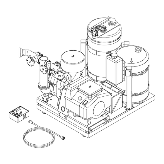
Page 6: Major Components Diagram
FLUSH TANK FUEL TANK FORMULATION ASSEMBLY ASSEMBLY TANK ASSEMBLY BATTERY NOZZLE BOOM ASSEMBLY GASOLINE ENGINE FORMULATION FILTER FORMULATION PUMP ENCLOSURE COUPLING GUARD NOZZLE BOOM PRESSURE GAUGE REMOTE CONTROL 3-WAY VALVE (FORM/FLUSH) BLOWER REMOTE CONTROL CABLE ASSEMBLY INTAKE AIR FILTER Maxi-Pro Major Components Diagram... -
Page 7: Forward
FOREWORD The application of insecticides is the predominant method by which man attempts to control the size of insect populations. Due to environmental and economical reasons, it is desirable to treat a given area with the least amount of insecticide that can be made to be effective. -
Page 8: Working Principles
WORKING PRINCIPLES An 18 Horsepower, electric start, four-cycle gasoline engine with a flexible coupling on its output shaft is used to drive a positive displacement rotary-blower. The air entering the blower is first filtered through a large stainless steel filtering element. The blower supplies air pressure to (4) nozzles. - Page 9 WORKING PRINCIPLES (Continued) All liquid conveying components such as tubing, fittings, pump, filters, and valves are made of corrosion resistant materials. The machine is equipped with a remote control unit that contains the following Machine ON/OFF switch • • Engine remote start switch •...
-
Page 10: Assembly Instructions
ASSEMBLY INSTRUCTIONS Uncrate the unit and remove all packing materials. NOTE: It is a good idea to retain the original machine shipping carton for storage. Place the remote control unit where it will not be damaged while the machine is being installed. Remove the machine from the shipping skid by removing the three lag screws that retain the shipping brackets. - Page 11 CAUTION NEVER FILL BATTERY IN MACHINE AS SPILLS WILL DAMAGE FINISH AND CAUSE PREMATURE CORROSION AND/OR DAMAGE TO COMPONENTS. Charge 12 volt battery at 3 - 4 amps until the acid temperature is above 80°F (26 °C), and the hydrometer reading is 1.250 or higher. Acid temperature must never exceed 125 °F while charging.
-
Page 12: Machine Installation
MACHINE INSTALLATION Remove the machine from the skid and lift the machine onto the vehicle with the discharge end of the machine toward the rear of the vehicle. Pass the remote control unit through an open window and locate it within reach of the person operating the machine. -
Page 13: Safety Precautions
SAFETY PRECAUTIONS WARNING READ AND UNDERSTAND THESE SAFETY PRECAUTIONS BEFORE OPERATING MACHINE ENGINE AND FUEL; This machine uses gasoline as the fuel for the internal combustion engine and all precautions commonly applying to this volatile fuel should be observed. Exercise extreme caution to avoid spilling of gasoline. If spillage occurs, wipe it off and allow evaporation time before starting the engine. - Page 14 SAFETY PRECAUTIONS (Continued) SAFETY EQUIPMENT: In addition to any safety equipment that may be required by the type of formulation which is being used, the following items should be mandatory for each vehicle which carries this machine during fogging operations. a.
-
Page 15: Operation
MACHINE OPERATION CAUTION READ THIS COMPLETE OPERATION SECTION AND THE SECTION ON SAFETY PRECAUTIONS BEFORE STARTING THE MACHINE FOR THE FIRST TIME. For first time operation, the sections on MACHINE INSTALLATION and MACHINE OPERATION must be performed before proceeding with this section. When operating this machine for the first time, move to an uncongested and well-vented work area away from flammable materials. -
Page 16: Pre-Spray Check List
PRE-SPRAY CHECK LIST Verify that the remote control box is within easy reach of the operator. Verify that the adjustable nozzle boom is in the correct position as required for the spraying operation to be accomplished, and that the ring damp which allows this positioning is tight. -
Page 17: Engine Preparation
ENGINE PREPARATION Oil Recommendations Change and add oil according to chart below. Do not overfill. Use high quality detergent oil classified "For service SC, SD, SE, SF, SG" as B&S "warranty certified" SAE 30 oil, part no. 100005. Use no especial additives with recommended oils. (*) Air cooled engines run hotter than automotive engines. -
Page 18: Starting The Engine
STARTING THE ENGINE CHOKE ENGINE: Move engine choke control to position lever in "choke" position (pulling the control rod). NOTE: This should fully dose choke on carburetor. Note: The manual choke is provided for cold starting of the engine. Once the engine has been allowed to warm-up, choking the engine should not be needed for restarting. -
Page 19: Liquid Flowability Measurement
MEASURING LIQUID FLOWABILITY (VISCOSITY) In order to achieve consistent results in generating aerosols with a volume-median- diameter (VMD) in the sub 20 micron range, several variables must be kept under control at the same time. The ability of an aerosol generator to consistently break up a liquid into appropriate sized droplets depends on (3) key elements: The available energy flow (air flow) through the nozzle is governed by the blower speed. - Page 20 To measure the flowability (viscosity) of your formulation: 1. Place a sample of the formulation liquid to be dispensed in the relative flowability meter provided with the machine such that the liquid level is above the top line. 2. Hold the meter vertical and allow the liquid to flow through the brass orifice at the outlet end of the meter into an appropriate container.
-
Page 21: Typical Insecticide Flow Rate
CAUTION Follow all warnings and cautions on your formulation label. Do not attempt to apply any formulation at a rate greater than what is specified on the formulation label. This includes driving your vehicle at a rate slower than what is specified. TYPICAL FLOW RATES FOR INSECTICIDES TABLE 1 FLOW... -
Page 22: Particle Size Tables
PARTICLE SIZE (VMD) IN MICRONS RESPECT TO FLOW RATE AND BOOM PRESSURE TABLE 2 DIBRON (NALED) (TIME THROUGH FLOW METER APPROX. 34 SECONDS) LIQUID LIQUID BOOM PRESSURE FLOW RATE FLOW RATE OZ/MIN ML/MIN 8PSI 6PSI 4PSI 3PSI 2PS1 4.7 VMD 5.7 VMD 8.4 VMD 10 VMD... -
Page 23: Syncroflow Section
SYNCROFLOW SYSTEM When equipped, the Curtis Syncroflow System allows you to dispense formulation at either a constant flow (“manual”) regardless of vehicle speed, or a variable flow ("syncroflow") which is correlated to vary proportionately with vehicle speeds from 0 - 20 mph (0-32 km/h). Either mode can be actuated by a toggle switch located on the side of the pump control box. - Page 24 Place the MODE switch on the remote control box in the SPRAY position. 8. Observe that, the MACHINE light and the SPRAY light are ON and the FLUSH, OUTPUT and FAULT Sights are not ON. The digital rate readout should reads zero. 10.
-
Page 25: Maintenance
PREVENTIVE MAINTENANCE NOTE: A successful maintenance program begins after the first use of the machine and not after the machine has ceased to function. PREVENTIVE MAINTENANCE: Occasionally inspect mounting hardware to ensure that fasteners are tight. Loose hardware can cause excessive vibration leading to major failure of components. -
Page 26: Maintenance Schedule
MAINTENANCE SCHEDULE TABLE 5 NOTE: Change oil more often when operating in high ambient temperatures. Clean air filters more often under dusty conditions or when airborne debris is present. See engine and blower manuals. -
Page 27: Flushing The System
FLUSHING SYSTEM The system must be flushed after each use to protect the equipment from the corrosive material in the formulation. CAUTION Never handle any parts on the that come in contact with formulation until the unit has been thoroughly flushed with isopropyl alcohol or other recommended flushing agent. -
Page 28: Formulation/Flush Solenoid Valve
3-WAY SOLENOID VALVE (FORMULATION/FLUSH) The corrosion resistant 3-way solenoid valve is located under the Nozzle Boom assembly (close to blower brackets) and is used as a selector to route either formulation (spray) or flushing solution (flush) from the respective tanks to the nozzles. This is accomplished by placing the “MODE”... -
Page 29: Formulation Filter
FORMULATION FILTER The system is equipped with an in line low profile filter located at the formulation tank standpipe. This filter is to prevent any foreign matter from entering the 3-way solenoid valve and the nozzle system. Located inside the filter housing is a fine mesh stainless steel screen and an Atlas gasket seal. -
Page 30: Blower Filter
FILTER - SILENCER (Rotary Blower) General: The air blower filter - silencer is mounted on the air blower. Dirt and other foreign particles are filtered from the incoming air by means of the reusable stainless element. The design is such that it partially silences the air also. Note: Do Not run the machine without this filter silencer assembly;... -
Page 31: Nozzles
ULV NOZZLE ASSEMBLY The design of ULV Nozzles is such that it should require little maintenance if the machine is properly flushed after each use. However, if it becomes necessary to clean the entire Nozzle Assembly, refer to steps 1-7. To inspect the inside of the Nozzle it is not necessary to remove the entire Nozzle Assembly from the machine. -
Page 32: 3-Way Solenoid Valve
3- WAY SOLENOID VALVE ASSEMBLY (INSTRUCTIONS FOR REBUILDING AND CLEANING) Using a screwdriver, snap off the retaining clip which secures the coil assembly. EXPLODED VIEW, 3-WAY SOLENOID VALUE Remove the retaining clip, the nameplate spacer and the coil housing. Slide the coil off the valve body, and using a spanner nut (P/N 62650-15), remove the core housing for cleaning or rebuilding. -
Page 33: Formulation Pump Calibration
PUMP - FLOW CALIBRATION The formulation pump is a magnetically coupled, rotary gear pump that maintains a consistent flow of fluid thru the nozzle system regardless of fluid temperature or viscosity. To check the output of the pump with respect to the digital readout on the remote control box: 1. -
Page 34: Flexible Coupling
HI-FLEX COUPLING INSTALLATION INSTRUCTIONS HI-FLEX COUPLING INSTALLATION INSTRUCTIONS FLANGE AND BUSHING INSTALLATION Make sure the bore and tapered cone surface of the bushing and flanges are free of all foreign substances such a paint or dirt. FLANGE AND BUSHING INSTALLATION Make sure the bore and tapered cone surface of the bushing and flanges are free of 1. - Page 35 CAUTION : Never allow the flange assembly to be drawn in contact with the flange of the ...
- Page 36 INSTALLATION OF FLEXIBLE ELEMENT/INSERT 5. You may loosen the flange assembly screws as much as possible without disassembly of cover or you may remove the screws completely thus FLEXIBLE ELEMENT disassembling the cover. In either case wrap the flexible element around ELEMENT’S BEAD the flange assembling.
-
Page 37: Storage And Shipment
STORAGE & SHIPMENT PREPARING THE BLOWER FOR STORAGE In preparing the blower for storage, the inner workings of the blower must be coated with a rust inhibiting oil. This is done by removing the air filter/silencer by turning it counterclockwise (CCW). After the filter/silencer is removed, access to the inner workings is possible. - Page 38 PREPARING THE BATTERY FOR STORAGE Disconnect positive (+) and negative (-) battery cables and wrap cable ends with electrical tape. Remove battery and store in a cool dry area. CAUTION WHEN DISCONNECTING OF THE BATTERY IS REQUIRED, REMOTE NEGATIVE (-) CABLE FIRST. PREPARING THE FRAME ASSEMBLY FOR STORAGE The frame should be wiped down with IsopropyI Alcohol and dried.
-
Page 39: Electrical Controls
ELECTRICAL CONTROL NOTE: The electrical controls do not require periodic maintenance but should be checked when the machine does not function properly. The electric controls consist of the switches, solenoid, read-out system, optical tachometer, valve and gear pump. Normal operation of the basic components is described below: 1. -
Page 40: Remote Control Box Functions
GEAR PUMPING SYSTEM TOGGLE SWITCH FUNCTIONS 1) Machine switch off: Removes +12 V DC system power and grounds engine ignition to kill engine. Machine switch on: Applies +12 V DC system power and removes ground from engine ignition. This position also applies power to machine L.E.D. - Page 41 SELECTOR SWITCH FUNCTIONS (Continued) Connects low rate readout in milliliters/minute to digital meter and located decimal point one place from right. Voltage of 54.0 millivolts corresponds to 54.0 ml/min. Connects high rate readout in milliliters/minute to digital meter and leaves decimal point blank. Voltage of 54.0 millivolts corresponds to 54.0 ml/min.
-
Page 42: Pump Control Assembly
PUMP CONTROL ASSEMBLY The pump control assembly contains the formulation pump, the control electronics, the manual/syncroflow switch, and the power fuse. FORMULATION PUMP: The formulation pump is a magnetically coupled stainless steel, gear pump driven by a DC motor. The DC motor is driven by the variable pulse width output of the motor control module. -
Page 43: Pump Control, Outside Diagram
OUTSIDE CONTROLS/COMPONENTS (Gear Pumping System) TO REMOTE CONTROL CABLE LOCKABLE LATCH MODE SWITCH (MANUAL OR SYNCROFLOW) TO MACHINE HARNESS TO RADAR SPEED SENSOR (SYNCROFLOW) FUSE BNC TESTING JACK (TACH SENSOR ON PUMP) TO AIR LINE “IN” PORT FROM BLOWER PUMP HEAD BASE “OUT”... -
Page 44: Power Supply Module
POWER SUPPLY MODULE The power regulator module takes the 12V DC battery power and converts it to 10:00 +/- .05 V DC and 5.00 +/- .12 V DC for use as references in the system. The metering accuracy is dependent on the accuracy of the + 10 V DC supply. This module also contains the reference amplifier which is analogous to the gallons of gasoline remaining. -
Page 45: Motor Control Module
MOTOR CONTROL MODULE The motor control module receives a command from the rate potentiometer located on the remote control box and generates a variable pulse width command to the formulation motor. The command signal is added to the feed back signal generated by the tachometer decode circuit and a difference amplified drives the variable pulse width generator. - Page 46 MOTOR CONTROL MODULE (Continued) Rate feedback Voltage from tach decode module which represents pumping rate: 3 to 6.2 V DC. See tachometer module pin Low rate OUT Pins 7 & 9 are used as junction only. +10.00 volts dc when output on switch is on. Pressure Control on switch must also be energized.
-
Page 47: Tachometer Decode Module
TACHOMETER DECODE MODULE The tachometer decode module senses the interruptions of the infrared sensor located on the motor which drives the formulation pump. The sensor is interrupted 40 times (the number of teeth on the sensing gear) with each revolution of the pump. These pulses are amplified and fed into two frequencies to voltage converters, one for low range and one for high range. - Page 48 TACHOMETER DECODE MODULE (Continued) -4VDC Power out to fuel reference amplifier in power regulator module. Generated by inverter circuit in tach module. Usually measures -4.00 +/- .15 volts. Power in from voltage regulator module measures 5.00 5 +5 V DC +/-.
-
Page 49: Speed Decode Module
SPEED DECODE MODULE The speed decode module is included in all machines equipped with the SYNCROFLOW option. This module is similar to the tachometer decode module in that it uses a frequency to voltage to converter and an external sensor to generate a pulse rate. The speed decode module is driven by a Hall effect sensor which is mechanically coupled to the transmission of the vehicle. - Page 50 SPEED DECODE MODULE (Continued) Sensor input Provide "sink" (solid state switch to ground) each time one of the magnetic poles on the monolithic magnet passes the Hall effect sensor, causing a voltage drop across the pull up resistor R 10 located on the speed decode module.
-
Page 51: Optical Sensor Interface
OPTICAL SENSOR INTERFACE The interface with the optical sensor is through the small 4 pin connector on the tachometer decode module. The signal references are as follows: REFERENCE TAB FUNCTION DESCRIPTION Buffered tachometer rate 0 to approximately 1200 Test pulses per second. +5 V DC limited by 180 ohms to drive the emission diode Sensor PWR in the optical sensor. -
Page 52: Mph Switch
4 MPH SWITCH MODULE The 4 mph switch module stops the output of formulation in the syncroflow mode when the vehicle speed slows to 4 miles per hour or below. This module measures the analog voltage output of the speed decode module and compares it to a reference voltage to determine if the speed is above, or below the preset level. -
Page 61: Bypassing The Pressure Switch
BY PASSING THE AIR PRESSURE SWITCH PRESSURE SWITCH RED WIRE ORANGE WIRE AIR PRESSURE FROM BLOWER PIECE OF TUBING PUMP AND CONTROL ASSEMBLY, P/N 64617-R (RELATIVE LOCATION OF PRESSURE SWITCH) The air pressure switch is part of the logic of the circuit, allowing the operation of the formulation pump only if the air nozzle boom pressure is present. -
Page 67: Engine Assembly 18 Hp Vanguard
18 19 20 ENGINE ASSEMBLY, P/N 62799-10 ITEM QUANTITY PART NUMBER ITEM DESCRIPTION 62799 ENGINE, 18 HP, VANGUARD 190254 NUT, 10-24 LOCK HEX 64016 HOURMETER / TACHOMETER 85685 CONNECTOR 3M 63285-1 CLAMP, CABLE 5/8 49078 HARNESS, ADAPTER (B&S) 63186 BOLT, M8-1.25 x 16, HEX 138485 WASHER, LOCK, 5/16, EXT 120393... -
Page 68: Solenoid/Bracket Assembly (Auto Choke)
SOLENOID/BRACKET AY 65085 (OPTIONAL ELECTRIC CHOKE) SOLENOID/BRACKET AY 65085 ITEM PART # DESCRIPTION 63182 BRACKET, SOLENOID CHOKE 53284 LINKAGE AY, CARBURETOR 134524 NUT, 4-40 HEX 159053 SCREW, 4-40 x 3/8 PHCRZ 65087 SOLENOID AY 85075 SCREW, 4-40 x ¾ 138522 WASHER, LOCK #4 INTO... -
Page 69: Blower Assembly
BLOWER ASSEMBLY P/N: 63461 ITEM QUANTITY PART NUMBER ITEM DESCRIPTION 62809 BLOWER, ROOT 5.45 62871 CUTPUT FLANGE AY 62826 ELBOW, INPUT 62824 NIPPLE, 2.5 NPT. X 3.5 62805 LOCKING RING 22183-8 RESTRICTING TEE 62851 FILTER SILENCER 139009 SCREW, SET, 1/4-28 X .25 63460-6 BUSHING, 7/8”... -
Page 70: Nozzle/Boom Assembly
NOZZLE/BOOM ASSEMBLY, P/N 62881 ITEM PART # DESCRIPTION 62866 NOZZLE ARM WELDED AY 62163 SCREW, 8-32 x 3/8 63019 CLAMP, V-INSERT 62861-2 TEE TUBE AY 67094-1 NOZZLE AY 62555-1 UNION ELBOW, ¼ T 62584-23 TUBING, 1/4 189772 SCREW, 10-32 x 3/8 HEX 138479 WASHER, #10 EXT 62556-1... -
Page 72: Flexible Coupling Assembly
FLEXIBLE COUPLING ASSEMBLY P/N 67087-3 ITEM QTY. PART NUMBER DESCRIPTION 62549 KEY, 1/4 X 1.75 63460-7 BUSHING, TYPE SH, 1” 67087 FLANGE AY., SH70 63460-6 BUSHING, TYPE SH., .875”... -
Page 74: Formulation Tank Assembly
SEE DETAIL DETAIL FORMULATION TANK ASSEMBLY W/ FILTER P/N 64004-1 ITEM PART # DESCRIPTION 62574 FORMULATION STANDPIPE AY 62545 FORMULATION STANDPIPE 62550-3 NUT, .375 STL GRIP 62573-2 CONNECTOR, MALE MOD. 63094 LABEL, FORMULATION 64077 CAP AY, MALE FILL 2″ 64002 TANK, 15G NAT POLY 64772 BUSHING, ¾... -
Page 75: Flush Tank Assembly
FLUSH TANK ASSEMBLY (1 GALLON), P/N: 63337-1 ITEM PART # DESCRIPTION 63302-6 TANK, 1 GAL. (MACHINED) 62592 LABEL, FLUSH 62553-1 CONNECTOR, UNION, 1/4 T 62550-1 NUT, .25, STEEL GRIP 114628 SLEEVE, 1/4 T 145463 NUT, 1/4 T 10105 CONNECTOR, STANDPIPE 53131 WASHER, FLAT 74288... -
Page 76: 3-Way Valve Assembly (Formulation/Flush)
3-WAY VALVE ASSEMBLY (FORM/FLUSH) P/N 62946 ITEM PART # DESCRIPTION 62650 VALVE AY, 3-WAY 62650-1 VALVE, 3 WAY SOLENOID 34065 HOUSING, PIN (2 CKT) 74282 PIN, SIDE FEED (REEL) 48066-4 TUBING, FLEX 3/8 DIA, 18″ L 62641-2 ELBOW, ¼ MP – ¼ T 62552-1 CONNECTOR, ¼... -
Page 77: Steel & Plastic Gripper Nuts
SAMPLE CONNECTIONS USING STEEL & PLASTIC GRIPPER NUT... -
Page 80: Machine Plumbing Diagram
MAXI-PRO Plumbing Diagram ITEM PART # DESCRIPTION 62582-3 NUT, 3/8 PLTC GRIP 62586-11 TUBE, 3/8 OD x 54″ 62582-1 NUT, ¼ PLST GRIP 62584-9 TUBE, ¼ OD x 53″ 62584-20 TUBE, ¼ OD x 21″ 62584-18 TUBE, ¼ OD x 17.5″ 145463 NUT, ¼... -
Page 81: Automatic Engine Idleback (Optional)
IDLEBACK KIT P/N 63875 ITEM QUANTITY DESCRIPTION 120854 BOLT HEX ¼-20 x 5/8″ 120392 WASHER, FLAT ¼ REG 121753 WASHER, LOCK ¼ EXTO 134551 NUT, HEX ¼-20 63850 SOLENOID, 12V DC 62693-140 WIRE ASSEMBLY, BLACK 20247 TIE, CABLE 63849 ENCLOSURE, RELAY 63874 BRACKET, SOLENOID 120367... -
Page 82: Blower Performance Curve
ROOTS Blower (URAI 45) Performance Curve 4 PSI 5 PSI 6 PSI 7 PSI 8 PSI 1750 2950 3550 Speed‐ Revolutions per minute... - Page 83 Notes: ________________________________ ________________________________ ________________________________ ________________________________ ________________________________ ________________________________ ________________________________ ________________________________ ________________________________ ________________________________ ________________________________ ________________________________ ________________________________ ________________________________ ________________________________ ________________________________ ________________________________...
- Page 84 Dyna-Fog Offers a Complete Assortment of Sprayers and Foggers PULSE-JET POWERED THERMAL FOGGERS: From 0-120 GPH (0-453 LPH) output. Our complete line include different models like the Superhawk, Golden Eagle, Trailblazer, Falcon, Patriot, Blackhawk, Mister III, SilverCloud and Model 1200. Portable or Truck mounted machines. Different models are available for Oil base or Water base formulations.
Need help?
Do you have a question about the MAXI-PRO 4 and is the answer not in the manual?
Questions and answers
Pump output is full blast, cant control output.
The pump output on the Curtis Dyna-Fog MAXI-PRO 4 can become uncontrollable if the speed exceeds 22 mph or if the output rate exceeds the selected instrumentation or control range. These conditions trigger the fault light and may indicate a loss of control over the pump output.
This answer is automatically generated