Advertisement
Table of Contents
- 1 Table of Contents
- 2 Introduction
- 3 General Description
- 4 Installation
- 5 Main Unit VSS-111
- 6 VSS-222 Microphones
- 7 Setting & Adjustment
- 8 General
- 9 Microphone Adjustment
- 10 Remote Muting When Using Own Typhoon
- 11 Adjustment of Squelch Function
- 12 Operation of the System
- 13 Specifications
- 14 Datasheet, Electrical & Mechanical Drawings
- Download this manual
Advertisement
Table of Contents

Related Manuals for Zenitel Vingtor VSS


Summary of Contents for Zenitel Vingtor VSS
- Page 1 Sound Reception System A100K10874 INSTALLATION & SERVICE MANUAL...
-
Page 2: Table Of Contents
Installation & Service manual VSS system Contents 1. Introduction .....................1 2. General Description ................2 3. Installation ....................3 3. 1 Main Unit VSS-111 ....................3 3.2. VSS-222 microphones ....................3 4. Setting & Adjustment .................4 4.1 General........................4 4.2 Microphone adjustment ..................... 4 4.3 Remote Muting when using own typhoon .............. -
Page 3: Introduction
2011.02.01 Updating of IP rating Zenitel Marine assumes no responsibility for any errors that may appear in this publication, or Zenitel Norway AS and its subsidiaries assume no responsibilities for any errors that may appear in this publication, or for damages arising from the information in it. No information in this publication should be regarded as a warranty made by Zenitel Norway AS. -
Page 4: General Description
Installation & Service manual VSS system 2. General Description The VSS system enable the navigator on a one 4 x VSS-222 man operated bridge to listen to the environmental sound signals from other ships or fog horns that are audible outside the ship when standing inside the enclosed bridge space. -
Page 5: Installation
Installation & Service manual VSS system 3. Installation 3. 1 Main Unit VSS-111 For physical dimensions, recommended panel cut-out, size of mounting holes etc. please see mechanical drawing VSS-111_dd. According to rules the system loudspeaker(s) should be installed so that incoming signals are audible at all positions inside the bridge. -
Page 6: Setting & Adjustment
Installation & Service manual VSS system 4. Setting & Adjustment 4.1 General The settings are factory adjusted and set to a level close to the real operation conditions as possible. But in order to optimise the performance of the system, may be the installation must be adjusted on site. -
Page 7: Operation Of The System
Installation & Service manual VSS system Remove cover for access to the potentiometer marked squelch. Use a screwdriver. In case of higher noise threshold level than factory adjusted. Turn potentiometer clockwise until the undesirable sound source not activates the system. Increase the signal from the sound source with approx.3 dB.(To simulate the real sound source) and check if the system activates. -
Page 8: Datasheet, Electrical & Mechanical Drawings
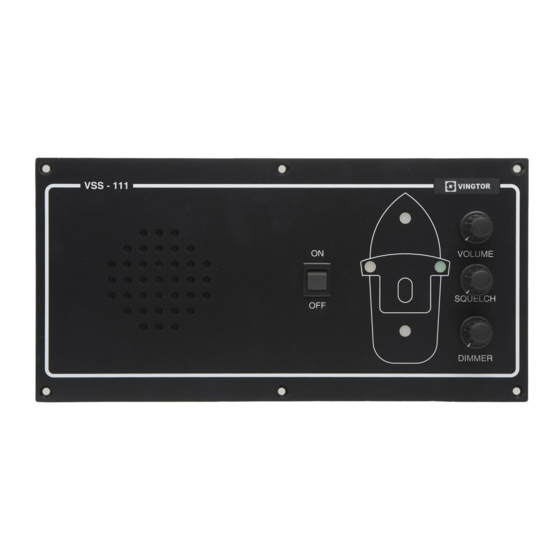
Installation & Service manual VSS system 7. Datasheet, Electrical & Mechanical drawings Cable diagram ......................Doc.no.GVSS CD1294B rev.04 Datasheet.............. VSS-111 ..............A100K10520 Dimension, mounting details........ VSS-111 ..........Doc.no.VSS-111_dd Rev.05 Datasheet.............. VSS-222 ..............A100K10521 Bracket for mounting VSS-222......Art.no.VM-1564 ......Doc.no.VSS-222_md rev.03 Circuit diagram Audio amplifier circuit....VSS-111 ........Doc.no.VSS-111_cd part 1 rev.04 Circuit diagram Sound reception detector.... - Page 10 vSS-111 MAIN STATION FEATurES ▪ Sound Reception system main unit ▪ Built-in system amplifier ▪ Inputs for four (4) VSS-222 microphones ▪ Built-in loudspeaker with manual volume control ▪ LED dimmer control ▪ Remote muting of the amplifier circuitry when the vessel’s own typhone is activated ▪...
- Page 11 03.02.2011 vINGTOr products are developed and marketed by Zenitel Norway AS. The company’s Quality Assurance System is certified to meet the requirements in NS-EN ISO 9001:2008. Zenitel Norway AS reserves the right to modify designs and alter specifications without prior notice, in pursuance of a policy of continuous improvement. © 2011 Zenitel Norway AS.
- Page 13 & Security Systems\Zenitel Marine VINGTOR products are developed and marketed by Zenitel Norway AS. The company’s Quality Assurance System is certified to meet the requirements in NS-EN ISO 9001:2008. Zenitel Norway AS reserves the right to modify designs and alter specifications without prior notice, in pursuance of a policy of continuous improvement. © 2011 Zenitel Norway AS.
- Page 19 Zenitel Marine Component List VSS-111-squelsh Order no. Description Q,ty ECAS EP 2002.11985-344 1/4W Resistor 1/4W Resistor R2,3,6,12 100k 1/4W Resistor 1/4W Resistor R5,7,8,10 1/4W Resistor 1/4W Resistor 1/4W Resistor Potensiometer 0,47uF Capasitor 4,7uF Capasitor C2,5 10uF Capasitor C3,6 Capasitor 100nF Capasitor...
- Page 20 Zenitel Marine Component List VSS-111 Order no. Description Q’ty 02A1001 1/4W Resistor R1,2,3,4,7,8,11,12,24,25,98 02A1002 1/4W Resistor R27,48-51 02A1003 100k 1/4W Resistor 02A1004 1/4W Resistor R40-43,52-55 02A2202 1/4W Resistor R31-32 02A2209 1/4W Resistor R28-29 02A3302 1/4W Resistor 02A3303 330k 1/4W Resistor...
- Page 21 Zenitel Marine Component List VSS-111 64H1262 640456-2 MTA pin header connector male 64H1264 640441-4 MTA pin header connector male 64H1912 640441-2 MTA pin header connector female 64H1913 640441-3 MTA pin header connector female 68B0001 Cable clip , small 68B1001 LIMB-10...
- Page 22 Zenitel Marine SPAREPART-KIT For VSS – system. Part No. VSS111S Parts No. Qty. Description 10A5242 BZX79C 12V ZENER DIODE 12D4011 IC 1411 CMOS 12E0071 IC TL 071 OP.AMP. 12E0833 IC LM 833 OP.AMP. 12E2876 IC LM 2876T POWER AMP. 22A0547...
- Page 23 A100K10874 STENTOFON and VINGTOR products are developed and marketed by Zenitel Norway AS. The company’s Quality Assurance System is certified to meet the requirements in NS-EN ISO 9001:2008. Zenitel Norway AS reserves the right to modify designs and alter specifications without prior notice, in pursuance of a policy of continuous improvement. © 2009 Zenitel Norway AS.
Need help?
Do you have a question about the Vingtor VSS and is the answer not in the manual?
Questions and answers