Table of Contents
Advertisement
Advertisement
Table of Contents

Related Manuals for Zenitel PHONTECH SR 8300 MkII


Summary of Contents for Zenitel PHONTECH SR 8300 MkII
- Page 1 USER MANUAL 8300 MkII Sound Reception System MARITIME: COMMUNICATION SYSTEMS...
- Page 2 8300 MkII Sound Reception Kit 4000019470 Publication Log Rev. Date Author Status Comments 13.8.2019 Published Zenitel doc no. A100K11918 Type Approvals The 8300 MkII Sound Reception System has been type approved by the MED, CCS, ABS, DNV and RMRS classification societies.
-
Page 3: Table Of Contents
CONTENTS Abbreviations General Standards Product Description System Description Technical Specifications Product Specification P-8300 MkII Display Unit Product Specification P-8301 MkII Microphone Unit Product Specification Junction Box Installation P-8301 MkII Microphone Unit P-8300 MkII Display Unit Electrical Connections Operating Instructions Operational Modes 5.1.1 Normal Mode 5.1.2... - Page 4 Web Interface 5.9.1 Home Screen 5.9.2 Network Settings 31 5.9.3 Audio Settings 5.9.4 System Log 5.9.5 Additional Options Testing 37 Calibration and Testing Maintenance Test and Maintenance Records Troubleshooting 39 Microphone Surveillance Failure LED Surveillance Failure Foghorn Detection Failure 40 Display Unit Boot Failure Warranty Warranty Claims...
-
Page 5: Abbreviations
The International Organization for Standardization kB/s Kilobytes per second Kilohertz Light-emitting diode Marine Equipment Directive Pulse code modulation PJTR Zenitel proprietary sentence Return Material Authorization number RTCP Real-time Transport Control Protocol Real-time Transport Protocol System function ID SOLAS Safety of Life at Sea... -
Page 6: General
Zenitel develops and manufactures professional and state-of-the art products and communication systems for usage on land and at sea. Zenitel supplies products and services that comply with the latest applicable standards. The use of modern test instrumentation and detailed test procedures ensures that you are supplied with quality products. -
Page 7: Product Description
User Manual 8300 MkII Sound Reception System 1 Product Description The 8300 MkII Sound Reception System is designed to: • Receive and detect foghorn sounds from other vessels and pinpoint the direction of the signal source. • Detect signals with a fundamental frequency ranging from 70Hz to 820Hz. •... -
Page 8: System Description
User Manual 8300 MkII Sound Reception System 2 System Description A Sound Reception System is an acoustical electronic navigational aid that enables an individual to hear sound signals from other ships like foghorns when standing inside a totally enclosed bridge space, in order to perform the lookout function as required according to the International Regulations for Preventing Collisions at Sea, 1972. -
Page 9: Technical Specifications
User Manual 8300 MkII Sound Reception System 3 Technical Specifications 3.1 Product Specification P-8300 MkII Display Unit Supply Voltage: Nominal 24VDC Maximum Power Consumption: System Power: Dimensions (W/H/D): 144 mm / 144 mm / 124 mm Weight: 0.85 kg Temperature Operating: -15 to + 55 °C Temperature Storage: -15 to + 55 °C... - Page 10 User Manual 8300 MkII Sound Reception System Figure 5: P-8300 MkII - dimensions top (depth/width) Figure 6: P-8300 MkII - dimensions...
-
Page 11: Product Specification P-8301 Mkii Microphone Unit
User Manual 8300 MkII Sound Reception System 3.2 Product Specification P-8301 MkII Microphone Unit Supply Voltage: Powered by 8300 MkII/+5VDC Dimensions (W/H/D): 317 mm / 338 mm / 317 mm Weight: 3.95 kg Temperature Operating: -25 to + 55 °C Temperature Storage: -25 to + 70 °C Humidity:... - Page 12 User Manual 8300 MkII Sound Reception System Figure 9: P-8301 MkII - Dimensions (Mounting Bracket) Figure 10: P-8301 MkII - Mounting Bracket...
-
Page 13: Product Specification Junction Box
User Manual 8300 MkII Sound Reception System 3.3 Product Specification Junction Box Dimensions (W/H/D): 120 mm / 78 mm / 104.5 mm Weight: 0.35 kg Ingress Protection: IP-67 Temperature Operating: -50 to + 90 °C Figure 11: Junction Box - 12-way with screen (optional) -
Page 14: Installation
The microphone unit should not be installed next to a sound reflective source or obstacle that may block sound from entering it in a straight line. NOTE: Zenitel recommends that you install the microphone unit in a typical lookout position. Figure 12: Mounting on the top Figure 13: Mounting on the side... -
Page 15: P-8300 Mkii Display Unit
User Manual 8300 MkII Sound Reception System 4.2 P-8300 MkII Display Unit IMPORTANT: Prior to fastening the unit to a console, connect both the power and microphone unit connectors. To mount the P-8300 MkII Display Unit: Find the appropriate location for mounting (bridge or similar structure). Degrease the console. -
Page 16: Electrical Connections
User Manual 8300 MkII Sound Reception System 4.3 Electrical Connections The cable from the P-8301 MkII microphone unit is a 3-meter cable with flying leads and must be wired to a junction box suited to the environment it is placed in. A cable from the junction box must be laid to the P-8300 MkII display unit. When connecting the microphone unit to the display unit, the cable must be terminated in the 11-pin microphone connector on the back of the display unit. - Page 17 Aft + core size. Yellow Aft - 2. A junction box is optional and can be supplied by Zenitel 3. To comply with EMC requirements, all cable shields must Grey Strb + be safely connected to the chassis as shown.
-
Page 18: Operating Instructions
User Manual 8300 MkII Sound Reception System 5 Operating Instructions 5.1 Operational Modes The P-8300 MkII display unit has four different operational modes. The volume and lighting can be adjusted. To switch between modes, do the following: • Press and hold the control button for 5 seconds. NOTE: Continuing to hold the button will advance you into the next mode. -
Page 19: Manual Listen Mode
User Manual 8300 MkII Sound Reception System 5.1.2 Manual Listen Mode In the manual mode, a user can listen to each of the four microphones individually. The sound from the active microphone plays through the speaker at all times in this mode. To activate the manual listen mode, do the following: 1. -
Page 20: Calibration Detection Mode
User Manual 8300 MkII Sound Reception System 5.1.3 Calibration Detection Mode Use the calibration detection mode to adjust the offset display. You would, for example, do this to adjust the offset of an incorrectly mounted P-8301 MkII microphone unit. To enter the calibration detection mode, do the following: 1. -
Page 21: Network Operations
User Manual 8300 MkII Sound Reception System 5.2 Network Operations The 8300 MkII performs multiple network operations according to part 450 of the IEC 61162 standard. This includes inter- device communication and logging. The transmission groups are mapped to the following multicast addresses and ports: Transmission Group Address Port Combination MISC... -
Page 22: Pjtr Sentence
User Manual 8300 MkII Sound Reception System 5.2.1 PJTR Sentence The PJTR sentence is a proprietary sentence that is used for communication between the master and slave P-8300 MkII dis- play units. The first parameter of this sentence is the sentence code for our proprietary sentences. The remaining parameters depend on the sentence code that is sent. -
Page 23: Hbt Sentence
User Manual 8300 MkII Sound Reception System The VOL sentence has one additional parameter: Description Type New volume setting An integer between 0 and 99 inclusive. Figure 27: Example, VOL proprietary sentence 5.2.1.3 HBT Sentence The P-8300 MkII sends a heartbeat (HBT) sentence once every 60 seconds. This sentence is sent to the MISC transmission group. -
Page 24: Ddc Sentence
User Manual 8300 MkII Sound Reception System 5.2.2 DDC Sentence The P-8300 MkII display unit listens for all display dimming control (DDC) sentences. Sentences may come from other units on the network by default from the MISC channel. When a DDC sentence is received, the display unit will adjust the brightness to the new level. Two variants of the DDC messages are supported: one with and one without the sentence status parameter at the end of the sentence. -
Page 25: Syslog Messages
User Manual 8300 MkII Sound Reception System 5.3 Syslog Messages When syslog network logging is enabled, syslog messages are sent to the network address specified in the web interface. Refer to the network settings for more information. The following table lists messages that are sent when there is a problem with the unit. Message ID Message Text Additional Information... -
Page 26: Error Indicator
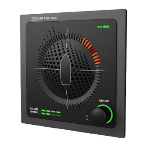
User Manual 8300 MkII Sound Reception System 5.5 Error Indicator When an error is detected, the status LED on the P-8300 MkII display unit lights up orange. Figure 22: Indicating an error is detected NOTE: For more information regarding potential failures or issues, refer to the section on Troubleshooting. 5.6 Detecting a Sound Signal When the P-8300 MkII detects a sound signal and determines the direction of the signal, the direction will appear on the display unit. -
Page 27: Detecting Multiple Sound Signals
User Manual 8300 MkII Sound Reception System 5.7 Detecting Multiple Sound Signals The P-8300 MkII is able to detect multiple sound signals simultaneously. Figure 25: Detecting multiple sound signals, 0˚ and 310˚ Figure 26: Detecting multiple sound signals 3 seconds after detection... -
Page 28: Adjusting Volume And Lighting
User Manual 8300 MkII Sound Reception System 5.8 Adjusting Volume and Lighting Both the volume and display lighting LEDs of the P-8300 MkII display unit are adjustable. NOTE: An orange LED displays the active state. This is also indicated by the lights on the left of the control button. To adjust the volume, do the following: 1. -
Page 29: Web Interface
User Manual 8300 MkII Sound Reception System 5.9 Web Interface The P-8300 MkII display unit has a web interface for logging and configuring the unit, and also supplies information regarding the state of the unit. The web interface can be accessed by entering the P-8300 MkII display unit IP address into any web browser. The default IP address is: 172.31.0.100 with a netmask of 255.255.255.0. - Page 30 User Manual 8300 MkII Sound Reception System Figure 29: Home screen, status OK - acknowledge messages Figure 30: Home screen, status Failed - Acknowledge messages...
-
Page 31: Network Settings
User Manual 8300 MkII Sound Reception System 5.9.2 Network Settings You can configure the following network settings: Configurable network settings Description Network address of the unit (3 options) 1. Static - this option allows you to configure any static network address along with the applicable netmask and gateway. - Page 32 User Manual 8300 MkII Sound Reception System Figure 31: Network settings - overall configuration...
-
Page 33: Audio Settings
User Manual 8300 MkII Sound Reception System 5.9.3 Audio Settings The audio settings of the P-8300 MkII display unit allows a user to adjust the signal-to-noise ratio required prior to a foghorn being detected. The default value is 2.25, calibrated to handle a foghorn where the bulk of the energy lies between 700-2100 Hz from 0.5 nautical miles when a horn creates a 111 dB SPL sound level. - Page 34 User Manual 8300 MkII Sound Reception System There are counters recording the number of IEC 61162-450 sentence errors received. There are six different types: Error types: Description: Invalid UDP headers Packets that have been received but are lacking the required IEC 61162-450 UDP header.
-
Page 35: Additional Options
User Manual 8300 MkII Sound Reception System 5.9.5 Additional Options The Additional options page contains configuration options that do not fall under any of the other categories. To adjust any of these options: 1. Select the applicable option. 2. Enter the applicable information. 3. - Page 36 User Manual 8300 MkII Sound Reception System Figure 34: Additional options, including maintenance (update firmware, reset and reboot)
-
Page 37: Testing
User Manual 8300 MkII Sound Reception System 6 Testing Testing should be done as required. 6.1 Calibration and Testing Testing of the operational functionality of the 8300 MkII is done using a foghorn. NOTE: The 8300 MkII automatically and continuously tests both the display and microphone unit. In the event of an error, the error will be displayed by the LEDs in the web interface or in the syslog server (if configured). -
Page 38: Test And Maintenance Records
User Manual 8300 MkII Sound Reception System 8 Test and Maintenance Records Record all test and maintenance activities below: Date M/T* Signature Inspection *M=Maintenance, T=Test. -
Page 39: Troubleshooting
3. Inspect the unit for physical obstruction of the failing microphone. NOTE: If you do not find any visible obstruction on the microphone, the unit should be consider damaged. In this case, contact Zenitel for support. Internal parts of the microphone unit are not serviceable. -
Page 40: Foghorn Detection Failure
Refer to the additional information under Additional Options. Warranty When purchasing a new 8300 MkII, the warranty period is valid for 2 years from the date the product is shipped from Zenitel. If you have a 8300 MkII and are unclear about your warranty period contact Zenitel. -
Page 41: Warranty Claims
Junction Box (optional) IMPORTANT: Ensure that all spare parts being fitted to the 8300 MkII are original spare parts manufactured or approved by Zenitel. Any use of counterfeit spare parts will deviate from the product type approval certificates. Recycling & Disposal The 8300 MkII is not to be disposed as normal waste and must be handled in accordance with the applicable waste disposal regulations in the country where the equipment is used. - Page 42 Document Number: A100K11918 Zenitel and its subsidiaries assume no responsibility for any errors that may appear in this publication, or for damages arising from the information therein. Phontech products are developed and marketed by Zenitel. The company’s Quality Assurance System is certified to meet the requirements in NS-EN ISO 9001. Zenitel reserves the right to modify designs and alter specifications without notice. ZENITEL PROPRIETARY. This document and its supplementing elements, contain Zenitel or third party information which is proprietary and confidential.
Need help?
Do you have a question about the PHONTECH SR 8300 MkII and is the answer not in the manual?
Questions and answers