
Subscribe to Our Youtube Channel
Related Manuals for Major Science Winpact SI-200

Summary of Contents for Major Science Winpact SI-200
- Page 1 Shaking Incubator Catalogue No. SI-200 www.majorsci.com service@majorsci.com V.03B ERSION 2015/12/10 SSUE 2017/03/21 EVISED...
-
Page 3: Table Of Contents
Table of Contents Table of Contents ......................... 3 Packing List ............................ 5 ............................6 ARNING Introduction ........................11 Product Specification ..................... 12 Component Guide ......................13 III. Installation Instruction ....................15 Installing Adjustable Angle Tube Rack (SI-200-02 / SI-200-03) ............15 Installing Universal Spring Rack (SI-200-04) ................... - Page 4 Troubleshooting ......................88 Troubleshooting Guide ..........................88 VII. Calibration & Maintenance ................... 91 Temperature Calibration ..........................91 Maintenance ..............................92 Allowance of Shaking/ Vibrating Settings ....................93 VIII. Ordering Information ....................96 Warranty ............................ 97...
-
Page 5: Packing List
Packing List Winpact Shaking Incubator × 1 Instruction Manual × 1 Power Cord x 1 Foot Stand (Pre-installed) x 4 Universal Platform x 1 ... -
Page 6: Warning
ARNING This equipment has been tested and verified to comply with safety limits. These limits are designed to provide reasonable protection against harmful interference when the equipment is operated in a commercial environment. This equipment may generate, use, and radiate radio frequency energy, and if not installed and used in accordance with the instruction manual, may cause harmful interference with radio communications. - Page 7 Science makes no claim that its instrument are designed or certified as medical device; no representation, promises, express warranty, or implied warranty will be made concerning the suitability of these instruments for any medical use. Major Science will not provide customers any notice or certification concerning its products being compliant as medical device.
- Page 8 CAUTION! Still Running! The shaker still runs after the cover has been opened. Wait for it to stop running. NOTICE! A torpedo level is needed before operation. To keep device as balanced as possible, it is recommended to apply a torpedo level especially necessary at the first time delivery, adjust the foot to ideal level (refer to p.33).
- Page 9 The Winpact Shaking Incubator has been designed for use with shielded wires thus minimizing any potential shock hazard to the user. Major Science recommends against the use of unshielded wires. 1. Dry out for a period of time and restore the instrument to NORMAL CONDITION before operation.
- Page 10 Equipment Operation Check that the device and all the accessories are assembled well and undamaged before starting operating. It is recommended that to have stopper for tubes user possesses before the operation to prevent any splitting of solution. NEVER access any HAZARDOUS LIVE parts that violate International Biosafety Regulations.
-
Page 11: Introduction
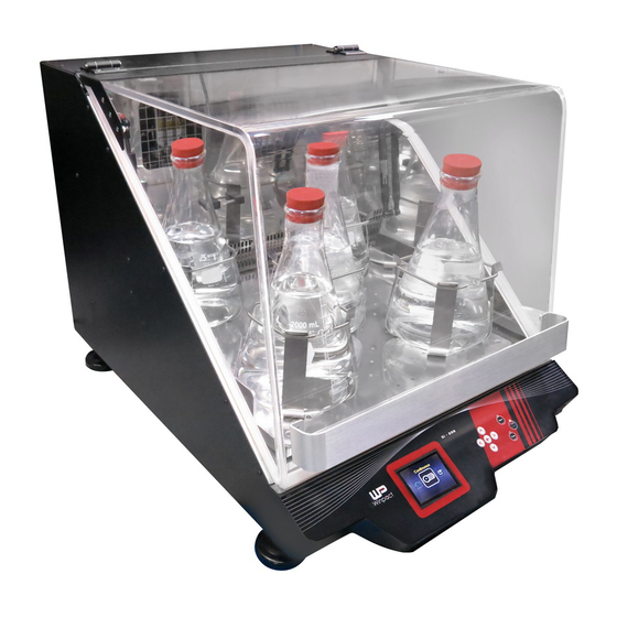
Introduction Major Science is introducing our newly innovated Winpact Shaking Incubator. The ultimate bench-top shaking incubator provides user the stability and durability for all user’s fermentation and incubation needs. Features Automatic shut off over temperature protection. Sensitivity adjustable G-sensor with warning embedded for imbalance weight detects. -
Page 12: Product Specification
II. Product Specification 23.3” ×32.3” × 20.9” Unit Dimension (Approx. 59 × 82 × 53 cm) Platform Size 18.1” x 18.1” (46 × 46 cm) Shaking Orbit 3/4” (19 mm) Speed Range 20 rpm – 500 rpm Speed Increment 1 rpm Communication Port RS485 External Temp. -
Page 13: Component Guide
III. Component Guide Transparent Shield Handle Power Switch Adjustable Foot Stand Control Panel Air/gas Inlet (optional) Spare Installation Hole RS-485 Voltage Switch 110/220 V Power Socket... - Page 14 PT-100 Sensor Port (External Temp. Port) Spare Installation Hole...
-
Page 15: Installation Instruction
To adapt different laboratory containers and experiment purposes, Major Science provides a variety of optional holders and trays for user. Its easy installation feature allows user to assemble the accessories on the platform by themselves. - Page 16 Flathead Screw Loosen the flathead screws on both ends of the rack. Lift up the rack from the bottom plate.
- Page 17 Place the bottom plate to the desired position on the platform. And use four truss-head screws and their corresponding M4 washer to fasten the bottom plate through the slots. M3 × 6mm The design of slots on bottom plate allows user to Slotted Head Screw arrange the tube racks in various angles without fixed...
- Page 18 Place the tube rack back to the bottom plate. Adjust the tilt angle of the rack before user fixes it on the bottom plate. A maximum of 4 tube racks can be installed on the platform.
-
Page 19: Installing Universal Spring Rack (Si-200-04)
Installing Universal Spring Rack (SI-200-04) ☝ Things Required: Universal Spring Rack (SI-200-04) M5 × 15mm Flathead Screws Phillip Screwdriver M5 × 15mm Phillip Screwdriver Universal Spring Rack (SI-200-04) Flathead Screw Remove four countersunk head screws at corners. (Put them away in the case of further usage) User can arrange the springs in any way for various requirements of... - Page 20 Place the spring rack on the platform, and fix it onto platform with four flathead screws. Leave the screws of the rest of corner untouched if only one spring rack is needed. Note: Spring rack should be fixed on either side on the platform, instead of on any place of platform.
-
Page 21: Installing Sticky Pad Platform (Si-200-05)
Installing Sticky Pad Platform (SI-200-05) ☝ Things Required: Sticky Pad Platform (SI-200-05) (With blue sticky pad 200 x 200 mm x 4 pcs.) M5 x 15mm Countersunk Head Screws x 4 pcs. M5 × 15mm Flathead Screws x4 pcs. ... - Page 22 Place the sticky pad platform onto platform then fix sticky pad platform with four countersunk head screws at the center and four flathead screws at corners. Note: The washable sticky pad can be stored by being covered with cling wrap (plastic wrap) when not being used.
-
Page 23: Installing Universal Cushioned Crossbar (Si-200-06)
Installing Universal Cushioned Crossbar (SI-200-06) ☝ Things Required: Universal Cushioned Crossbar (SI-200-06) (With silicone cushioned pad 455 x 415 mm x1 pce) M5 × 15mm Flathead Screws (the numbers of screws depend on the numbers of crossbars.) Phillip Screwdriver Universal Cushioned Crossbar &... - Page 24 Insert the bars into the rails on both ends of crossbar platform. Rail Crossbar Platform Crossbar End Crossbar Crossbar The 2 ends contain 2 screw holes respectively. The holes should face upward when user insert them into the rails. Rail Screw Hole...
- Page 25 Flathead Screw Use the provided flathead screws to fasten the crossbar on the platform. Remember to adjust the distance of the 2 crossbars based on user’s personal requirement such as the size of flasks. Four countersunk head screws at the center and four flathead screws at the corners when assembling the crossbar platform.
-
Page 26: Installing Microplate Holders (Si-200-07)
Installing Microplate Holders (SI-200-07) ☝ Things Required: Microplate Holders (SI-200-07) M4 × 6mm Truss Screws × 4 pcs. (With M4 Washer) Phillip Screwdriver M4 × 6mm Truss Head Screw Microplate Holders Phillip Screwdriver and M4 Washer Place the microplate holder on platform, and fasten the microplate holder with screws as well as M4 Washer with a screw driver onto the platform. - Page 27 A maximum of 9 microplate holders can be installed if the same type of holders is used.
-
Page 28: Installing Flask Holder (Si-200-08~13)
Installing Flask Holder (SI-200-08~13) ☝ Things Required: Flask Holder (50/ 125/ 250/ 500/ 1000/ 2000 ml) in the number of user’s requirement Phillip Screwdriver Phillip Screwdriver M4 × 6mm Truss Head Flask Holder Screw and M4 washer Apply the installation of flask holder to all types of flask holder with reference of the figure below. - Page 29 50 ml FLASK x 52 SI-200-08 Maximum 52 50ml-flask holders for one platform. NOTE: Try to keep the platform as balance as possible to ensure the longevity of bearings and belt. 125 ml FLASK x 25 SI-200-09 Maximum 25 125ml-flask holders for one platform.
- Page 30 250 ml FLASK x 25 SI-200-10 Maximum 25 250ml-flask holders for one platform. NOTE: Try to keep the platform as balance as possible to ensure the longevity of bearings and belt. 500 ml FLASK x 16 SI-200-11 Maximum 16 500ml-flask holders for one platform.
- Page 31 1000 ml FLASK x 9 SI-200-12 Maximum 9 1000ml-flask holders for one platform. NOTE: Try to keep the platform as balance as possible to ensure the longevity of bearings and belt. SI-200-13 2000 ml FLASK x 5 Maximum 5 2000ml-flask holders for one platform.
- Page 32 Flexible Arranging Possibility Example: User can select and arrange the universal platform with flexibility. 500ml 125m 1000ml 250m 2000ml...
- Page 33 For the flask of 1000 and 2000 ml, it is suggested to have spring band which is included with the purchase of 1000/2000 ml flasks to prevent any leakage or over deviation while device is under operation, especially at the high speed. For the rest of types of flasks, it is suggested to have a cable tie to make sure flasks are firmly fixed with flask holder on the plate.
-
Page 34: Adjusting The Foot Stand
Adjusting the Foot Stand ☝ Prepareaion: Winpact Shaking Incubator (SI-200) 25-27mm Chrome Wrench Chrome Wrench Winpact Shaking Incubator (SI-200) To stable the device when it is operating, user can adjust the foot stands to balance the device on the floor or lab bench. - Page 35 The 1 There are 2 nuts on each adjustable foot The 2 stand. Rotating the first nut in clockwise with 25-27 mm chrome wrench to loosen the foot stands. Rotating the second nut either clockwise or counterclockwise with 25-27 mm chrome wrench to the favorable height.
-
Page 36: Operation Instruction
V. Operation Instruction Winpact Shaking Incubator provides 2 types of operation modes for user to meet most of user’s experiment needs. Generally, the first image user see after turning on the incubator displays 3 options: Program, Continuous and System Setup. In this chapter, we will elaborate all the functions with 5 sections: features of control panel, program mode settings, continuous mode settings, system setup and remote control operation. -
Page 37: Features Of Control Panel
Features of Control Panel LCD Screen Key Pad ○ ○ ○ ○ ○ ○ ○ ○... - Page 38 Numbers Description Function Selection Key (Upward) - Press ○ to move upward. Selection Key (Leftward) - Press to move leftward. ○ Return Key - Press to return to last page. Selection Key (Downward) - Press ○ to move downward.
-
Page 39: Program Mode Settings
Program Mode Settings Winpact Shaking Incubator allows user to setup the schedules based on user’s requirement in Program Mode. Press to enter the setting page of different programs. -
Page 40: Naming The Program Mode Operation
Naming the Program Mode Operation In Program Mode page, Press to name user’s first program; user will see the first letter is flashing . Press to choose the letters, numbers, punctuation marks or space. When user have decided the first letter, press to move on to the next letter, and use to select the letter user want;... -
Page 41: Setting Up The Program Parameters
*Note (2): User can set up the program name in 8 letters. Each letter contains 94 options, including English capitals, lowercases, numbers, punctuation marks and space. The system can store up to 10 programs. Setting Up the Program Parameters After deciding the program name, press to confirm the adjustment and the letter will stop flashing. - Page 42 Every program contains 9 loops, and a loop consists of 3 steps. Each step allows user to set up the running time, shaking speed and incubator temperature. The symbol represents “Cycle”, which is related to the repetition of EACH LOOP. The maximum value of “Cycle”...
- Page 43 Switch to “step” column to set up all the parameters in each step. Select the step by pressing . Push and then to set up the running time. to adjust the numbers; then press to move from the hour and the minute parameter. After finishing the time setting, push to confirm the adjustment.
-
Page 44: Starting The Program Mode Operation
Starting the Program Mode Operation After setting up all the parameters, press in the left side of control panel to start up the operation based on user’s settings. The screen will show up the current status of incubator, as the picture below. The current-operating program Loop... -
Page 45: Continuous Mode Settings
Continuous Mode Settings In addition to Program Mode, Winpact Shaking Incubator allows user to use Continuous Mode to run the experiment under the specific circumstance. User can manually control the incubator temperature, shaking speed and operation time according to the experiment condition. -
Page 46: Setting Up The Continuous Mode
Setting Up the Continuous Mode Press to adjust the temperature value; the numbers on the left side of the screen will start flashing. Use to increase or decrease the value. Press again to confirm the set temperature. Then press to continue to shaking speed setting, and adjust the value in the same way that user adjust the temperature. -
Page 47: Starting The Continuous Mode Operation
Starting the Continuous Mode Operation In Continuous Mode, user can choose to start up either the heating or shaking operation by pressing either . Or user can have both of the heating and shaking operated by pressing When user starts the operation, the screen will switch to the monitor page to check the status of all parameters, like the picture below. - Page 48 *Note (7): If user wants to increase or decrease the running time in the middle of the operation, the ongoing time will be calculated in the new setting. Take the timeline drawn below for example, the original setting is 3 hours, but when the device has run for 1 hour, user changed the running time to 5 hours.
-
Page 49: System Setup
System Setup In System Setup page, user can activate the optional device, check the total operation time, calibrate the parameters and acquire other system information. Press to enter System Setup page. Then use to move from the settings and information. Press to go into each setting page. -
Page 50: Optional Device: Pt-100
Optional Device: PT-100 If user has purchased our Winpact Temperature Probe, user can install it on Winpact Shaking Incubator to increase the accuracy of temperature measurement, for example, the temperature in the flasks environment. Before user changes the system setting, make sure that user has installed the temperature probe correctly. -
Page 51: Temperature Permissible
Temperature Permissible Press to enter the setting page of Temperature Permissible. This page allows user to adjust the temperature permissible range for heating detection. - Page 52 Press again to edit the value. The permissible value ranges from 0℃ to 5℃, which the minimum unit is 0.1℃. Use to increase or decrease the number. The device will detect the incubator temperature according to the permissible value user set.
-
Page 53: System Total Operation Time
System Total Operation Time This page will record and present the total operation time of user’s shaking incubator from the first time user use. The timer counts up once the operation starts (either heating or shaking, or both). The minimum unit of the presented format is minute. The maximum value of days is 9999. -
Page 54: System Software Version
System Software Version Press to go into the information page of system software version. This page shows the using software version of user’s Winpact Shaking Incubator. Press to exit the page. -
Page 55: System Calibration Value
System Calibration Value Press to enter the page of system calibration information. The page is for maintenance and factory detection use only. Users are not allowed to edit or adjust the values. Press to exit the page. -
Page 56: Machine Id
Machine ID Press to enter the page of machine ID for editing the device number. If user has more than one SI-200 to use, user can set up the machine ID to distinguish them when several devices are connected to user’s personal computer. Press to edit or change the machine ID and use to adjust the... -
Page 57: Remote Control Operation
Remote Control Operation Except operating and adjusting the device directly on the device, user can install the associated software of SI-200 on user’s personal computer, and operate the device through the computer. Installing SI-200 Software on User’s Personal Computer Follow the steps below to correctly install the software on the computer. Step1 Insert the disk into the CD drive of user’s computer or laptop. - Page 58 Step3 The installation dialogue will pop up on the screen. Press “Next” to start installing. Step4 Read the license agreement and check “I Agree” to accept the terms. Click “Next”, continuing the installation. Or user can select “Cancel” to exit the installation dialogue.
- Page 59 Step5 Press “Browse” and select the folder to install the program. The default folder is set at “C:\Program Files (x86)\Major Science\SI-200\”. Or user can skip this step, directly to Step6.
- Page 60 Step6 Click “Next” to start the installation. Step7 The dialogue will show the installation status. Just wait for the installation to complete.
- Page 61 Step8 When the installation complete, press “Close” to exit the installation dialogue.
-
Page 62: Using Si-200 Software To Operate The Device
Using SI-200 Software to Operate the Device After the installation completes, user can find a “WP” icon (as the image below) on user’s desktop. Double-click the icon to start the remote control operation. *Notice: User will need to use the USB cable to connect the device with user’s computer before starting the remote control operation. - Page 63 ○ ○ Here we divide the SI-200 software interface into 3 parts, which function will be explained thoroughly in the following sections. Contains file name settings, software information and the ○ Top Bar number of devices. Displays the connection status, the selection of modes ○...
- Page 64 Remote Control Function Introduction ○ A Top Bar ○ A .1 ○ A .3 ○ A .2 ○ A .4 ○ A .1 File Name Settings Press “Option” to set up the data file name format . An option dialogue will pop up, adjust the settings based on user’s requirement.
- Page 65 ○ A .2 ReScan the Device If the device has once disconnected, press “ReScan Device” to help the software find the reconnected device. ○ A .3 Software Information Click “About” to see user’s SI-200 software version. ○ A .4 Device Number The displayed device number is based on the setting in “Machine ID”...
- Page 66 ○ B Status Column ○ B .1 ○ B .2 ○ B .3 ○ B .4...
- Page 67 ○ B .1 Connection Status This area displays the connection status between SI-200 and user’s personal computer. If the light appears in red, it means the device is not detected and the computer doesn’t connect to it. If in green, it indicates the connection is successful. Connected Disconnected ○...
- Page 68 Click it to start running the device. Click it to stop the operation. ○ B .4 Exit Button Click “Exit” to leave the remote control program. ○ C Setting & Record Column ○ ○ ○ There are 3 different tabs in this column: Chart ( C .1), Setting ( C .2), and History ( C .3).
- Page 69 ○ C .1 Chart The function of Chart tab is mainly for viewing the running data and monitoring the current status of heating and shaking speed. ○ C .1-a ○ C .1-b ○ C .1-c ○ C .1-d ○ C .1-e ○...
- Page 70 ○ C .1-a Curve Indication Column This area helps user distinguish the curves of different parameters in the running chart. Set Value of Temperature Present Value of Temperature Set Value of Shaking Speed Present Value of Shaking Speed Present Value of Temperature Set Value of Temperature Present Value of Shaking Speed Set Value of Shaking Speed...
- Page 71 ○ C .1-b Value Indication Column The program will display user’s set values* and the current condition in this section. User can compare the values with the curves in chart. *Note (10): In this column, all the values are unchangeable. If user attempts to adjust the set values, user has to stop the device and enter the setting tab to edit the parameters.
- Page 72 ○ C .1-c Record Period Column User can only edit the record period when the device is idled. Once SI-200 starts running the operation, user won’t be able to change the record period. User can edit the value of record period in the “Option” dialogue. *Notice: Remember to click “Apply”...
- Page 73 Image 1 (Unit) The time scale ranges from the minimum 10 (minute) to maximum 30 (minutes; in this moment, the operation time is 56 minutes in total, so the maximum can only be set at 56 at most.) When the option of “Unit” is The chart will only show the part in the set range selected, the settings of time of recorded data (which in this case, is the data...
- Page 74 Image 2 (All in Standard) The recoded data will be concentrated in 1 sheet of the chart if user applies the time scale to “All in standard” When the option of “All in option. And the time scale will increase standard”...
- Page 75 ○ C .1-f Reset Button Press “Reset” to return to the default setting. ○ C .1-g Apply Button Press “Apply” to confirm the new settings. ○ C .1-h Chart Printing Button Press “Print Chart” to print the current-viewed chart. ○ C .1-i Chart Column View the current trend of user’s operation in the chart column.
- Page 76 ○ C .2 Setting Switch to “Setting” tab to edit or change the parameters of different modes. ○ C .2-a ○ C .2-b ○ ○ C .2-c C .2-d...
- Page 77 ○ C .2-a Programmable Mode Setting User can set up the parameters of up to 10 programs in Programmable Mode. The setting concept of each program is consistent with the setting on the device. Edit the column to input user’s desired program name.
- Page 78 ○ C .2-b Continuous Mode Setting The setting method is same as the method user use on device. The incubator temperature during the operation. Range The shaking speed from 15 to 65 ℃ ℃. during the operation. Range from 20 to 500. The running time of the operation.
- Page 79 ○ C .2-d Download Button Press “Download” if user have changed or edited the settings of the 2 modes on device; the system will deliver the new settings to the SI-200 software on user’s computer. ○ C .3 History ○ C .3-a ○...
- Page 80 “History” tab is very similar to “Chart” tab. “History” tab allows user to review user’s recorded data on the computer. ○ C .3-a Curve Indication Column This area helps user distinguish the curves of different parameters in the running chart. Set Value of Temperature Present Value of Temperature Set Value of Shaking Speed...
- Page 81 ○ C .3-b Open File Button Click “Open File” to choose the data* that user would like to review on the computer. Log files *Note (13): Only log files can be viewed on the chart. *Notice: When user has chosen the desired file, click “Open” to load the file onto the chart.
- Page 82 The minimum of temperature scale in the chart. The maximum of temperature scale in the chart. The minimum of speed scale in the chart. The maximum of speed scale in the chart. The minimum of time scale in the chart The maximum of time scale in the chart *Note (14):...
- Page 83 Image 1 (Unit) The time scale ranges from the minimum 0 (minute) to maximum 64 (minutes; in this case, the operation time is 64 minutes in total, so When “Unit” is selected, the maximum can only be set at 64 at most.) the settings of time scale will influence the curve shape.
- Page 84 Image 2 (Unit) The time scale is set at the range from the minimum 30 (minute) to maximum 50(minutes; When “Unit” is selected, in this case, the operation time is 64 minutes in total, so the maximum can be set at 64 at the settings of time scale will influence the curve most.) The chart will only show the part in the...
- Page 85 Image 3 (All in Standard) The 64-minute recoded data will be concentrated in 1 sheet of the chart if When “All in standard” is user applies the time scale to “All in selected, user won’t be able standard” option. to edit the range of time scale.
- Page 86 Image 4 (All in Scale) The time scale is set at the range from the minimum 0 (minute) to 40 (minutes; in this case, When “All in scale” is the operation time is 64 minutes in total, so the selected, the settings of time maximum can be set at 64 at most.) The data in scale will influence the curve the range user set will display in 1 sheet of the...
- Page 87 ○ C .1-e Reset Button Press “Reset” to return to the default setting. ○ C .1-f Chart Printing Button Press “Print Chart” to print the current-viewed chart. ○ C .1-g Apply Button Press “Apply” to confirm the new settings. ○ C .1-h Chart Column View the current trend of user’s operation in the chart column.
-
Page 88: Troubleshooting
VI. Troubleshooting Common problems user might encounter are listed in the below. Users might have the problem solved by following the troubleshooting guide and the replacement instruction below. If the instructions cannot help user solve the problems, please contact the local representative or distributer for further assistance. - Page 89 The following table provides user the information of each warning and the corresponding solution. Should this table not solve user’s problem, please contact the service department of Major Science for further assistance. DO NOT disassemble the product by themselves in case of any injury or damage.
- Page 90 Warning pops up. System The recirculating fan Contact the service shut off automatically. Press is not working during department of Major enter to turn off the the operation. Science for maintenance. warning. Warning pops up. System The platform is not Contact the service shut off automatically.
-
Page 91: Calibration & Maintenance
VII. Calibration & Maintenance This chapter provides simple instructions on the temperature calibration and daily maintenance. Check the following sections for detailed information. Temperature Calibration Winpact Shaking Incubator offers users an easy way to calibrate the temperature sensor on their own. Follow the instruction below to finish the temperature calibration. Step 1. -
Page 92: Maintenance
Step 2. After user releases the button, the screen will enter to the temperature calibration page. Step 3. to choose which temperature sensor user wants to calibrate. Internal To calibrate the internal built-in temperature sensor of Winpact Shaking Incubator. External To calibrate the external device (PT-100). -
Page 93: Allowance Of Shaking/ Vibrating Settings
Allowance of Shaking/ Vibrating Settings To prevent system over-shaking due to unexpected hardware malfunction, the manufacturer has implemented a preventive mechanism defined in the six parameters to detect the abnormality and respond immediately by shutting down the system. For example, if the device is working on an uneven surface, the warning of over shaking can remind users and encourage users to arrange a proper working environment for the device. - Page 94 Step2 Hold the enter key until the number counts to the range of 100 to 500. (Pressing and hold at the same time to fast forward to the favorable number) Release the button when the number goes between 100 and 500 In this page, there are six parameters: PD and frequencies of Axis X, Y, and Z.
- Page 95 NOTE: Value of axis X/Y/Z PD is corresponding with the values of axis X/Y/Z frequency respectively. to switch to the parameters and press to enter the corresponding values. Use to increase or decrease the value. Press to store the settings.
-
Page 96: Ordering Information
VIII. Ordering Information Models Catalogue No. Description SI-200 Winpact Shaking Incubator Accessories Catalogue No. Description SI-200-01 Universal Platform SI-200-02 Adjustable Angle Tube Rack (33 × 15ml) SI-200-03 Adjustable Angle Tube Rack (16 × 50ml) SI-200-04 Universal Spring Rack SI-200-05 Sticky Pad Platform SI-200-06 Universal Cushioned Crossbar SI-200-07... -
Page 97: Warranty
This warranty excludes damages resulting from shipping, misuse, carelessness, or neglect. Major Science’s liability under the warranty is limited to the receipt of reasonable proof by the customer that the defect is embraced within the terms of the warranty. All claims made under this warranty must be presented to Major Science within one year following the date of delivery of the product to the customer.
Need help?
Do you have a question about the Winpact SI-200 and is the answer not in the manual?
Questions and answers