
Subscribe to Our Youtube Channel
Related Manuals for GÖLZ TS250A


Summary of Contents for GÖLZ TS250A
- Page 1 Translation of the Original Operating Manual Tile cutting machine – TS250A Read operating manual before starting any work! Keep the operating manual for future use! (086) 1 / 73...
- Page 2 Revision Date Chapter Reason for change Person responsible 05-20 Reissue Design Revision status: 05.2020 Serial number: © Gölz GmbH Dommersbach 51 D- 53940 Hellenthal Tel.: +49 (0)2482 – 12 200 Fax: +49 (0)2482 – 12 222 email: info@goelz.de website: www.goelz.de 2 / 73...
- Page 3 4.11 Installation site requirements ......................19 4.12 Storage requirements ........................19 5 Design and function ..........................20 Scope of delivery and responsibility ....................20 TS250A ............................20 5.2.1 Functional description ......................21 6 Transport & packaging ..........................23 Transport safety information ......................23 Transport inspection ........................
- Page 4 Content Location ............................26 Connection ............................27 First commissioning and acceptance, general ................27 7.4.1 Steps before commissioning ....................27 7.4.1.1 Mounting a cutting wheel ..................27 7.4.1.2 Fill the water tank ..................... 28 8 Operation ..............................29 Operation safety information......................29 Intended working position of the operator ..................
- Page 5 Content 13 Wiring diagram............................70 14 Index ................................71 EU conformity declaration ..........................73 5 / 73...
-
Page 6: Explanation Of Symbols
General General Operating manual This operating manual provides guidance on safe and efficient operation and should form a basis of any actions involving the machine. It is an integral part of the machine, which should be kept in the immediate vicinity accessible for its operating personnel. Prerequisite of safe operation is adherence to all safety and handling instructions. -
Page 7: Tips And Recommendations
General WARNING: ... draws attention to potentially dangerous situations that, if not avoided, may cause heavy or even fatal injuries. CAUTION! ... draws attention to potentially dangerous situations that, if not avoided, may result in slight injuries. ATTENTION! ... draws attention to potentially dangerous situations that, if not avoided, may result in material damage. -
Page 8: Warranty
General Unauthorised conversions Technical changes Use of non-approved spare parts The responsibilities agreed in the delivery contract, the General Terms and Conditions as well as the delivery conditions of the manufacturer and the statutory regulations valid at the time of the conclusion of the contract shall apply. - Page 9 Safety Safety This section provides an overview of all safety aspects of protection of operators and users from potential dangers, and safe and trouble-free operation. Disregarding these handling instructions, warnings and safety instructions may pose serious risks. Intended use The TS 250A tile cutting machine is designed exclusively for the following purposes in the commercial sector: The TS 250A tile cutting machine ...
-
Page 10: Responsibilities Of The Personnel
Safety Responsibilities of the operator Operator An operator is every natural or legal person, who uses the machine or delegates its use to others and is responsible for the safety of the user, personnel or third parties in the course of such use. Operator's duties The machine is used in the commercial sector. - Page 11 Safety Moreover, scope of responsibility of every person operating the machine includes the duty of always keeping it in a technically perfect condition, performing maintenance, according to the intervals specified, controlling all safety mechanisms for completeness and functionality on a regular basis. Personnel requirements Fundamentals Any operation with the machine may only be carried out by the persons, capable of performing their...
-
Page 12: Personal Protective Equipment
Safety Personal protective equipment Wearing personal protective equipment is required during the work. (1) Helmet with ear protectors (2) Visor or protective goggles (3) Dust mask / respirator (4) Safety gloves (5) Suitable protective clothing (6) Protective footwear with protection NOTE! It is prohibited to wear protective gloves near rotating parts, which pose the danger of pinching. - Page 13 Safety Movable parts CAUTION! Risk of injury by pinching in movable parts! Failure to wear appropriate protective equipment may lead to heavy injuries. Wear protective gloves Lock the cutter head Lock the guiding bridge 3.7.2 Risks through electrical hazards Electric current DANGER! Danger to life from electric current! Touching live parts leads to death.
-
Page 14: Safety Devices
Safety 3.7.5 Risks due to hazardous substances CAUTION! Risk of injury by hazardous substances, such as dust and cutting water or slurry! Failure to wear appropriate protective equipment may lead to damage to health. Use personal protective equipment Renew the cutting water regularly Use the dust mask Connect water supply 3.7.6... -
Page 15: Spare Parts
Safety Spare parts WARNING: Risk of injury due to wrong spare parts. Wrong spare parts can seriously compromise safety and cause damage and malfunction up to total failure. As a matter of principle, only original spare parts must be used. Original spare parts can be obtained via an authorised dealer or directly from the manufacturer. - Page 16 Safety Danger of cutting damage CAUTION! Risk of cut injuries! Reaching into moving tools may lead to heavy injuries. Do not touch rotating cutting wheels in any circumstances De-energise the machine before replacing the cutting wheel Illegible signs CAUTION! Risk of injury due to illegible symbols! Stickers and signs that got illegible, make danger zones insufficiently recognisable and may become incapable of indicating potential injury risks.
-
Page 17: Technical Data
Technical data Technical data Dimensions of the machine Dimensions of the cut piece Specification Value Unit Specification Value Unit Length max. length 1640 1300 Width max. width Height 1299 max. height Empty weight max. weight Operating weight Connection and motor values Other data Specification Value... -
Page 18: Operating Conditions
Technical data Operating conditions Working zone Specification Value Unit Temperature range Ambient temperature 5-45 ° C Relative air humidity, maximum (without condensing) Only operate the machine tool in the dust-free environment! Avoid direct impact of dampness, dust and frost. Conditions Do not operate in strong electric and magnetic fields! Do not operate the machine tool in explosive atmosphere! Cutting wheels... - Page 19 Technical data 4.10 Type plate The type plate is located on the base frame of the machine tool. 4.11 Installation site requirements The floor surface must: have sufficient load bearing capacity, be slip proof, be level. Installation conditions Choose the installation site as per space requirements according to the technical data. NOTE! The machine is designed for use in daylight.
-
Page 20: Design And Function
Upon transfer to the operator, the responsibility for safe handling and instruction of the personnel passes to the operator. The manufacturer offers training on the machine. The scope of delivery includes the following components: Components Quantity Tile cutting machine TS250A Technical documentation Optional accessory Quantity Lateral extension T-Lock tile clamp... -
Page 21: Functional Description
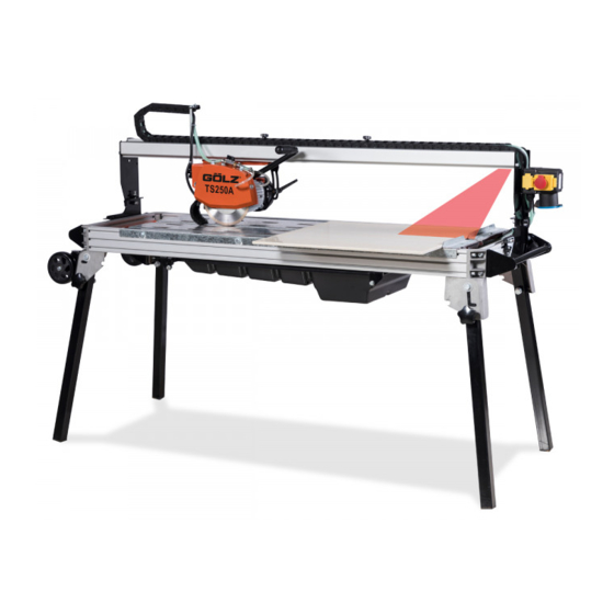
Design and function Base frame The base frame (1) is a sturdy aluminium construction. Cutter head The cutter head (2) is a welded steel structure; the motor (14) and the blade guard (3) are fixed to its bridge. It can be continuously pivoted 45° (Jolly) using the angle adjustment (16) and thus allows mitre cuts. - Page 22 Design and function The cutter head handle serves to manually regulate the drive speed when the cutter head’s rotating blade is being pulled through the material to be cut. The cutting process is finished when the material is cut through and the cutter head’s stop point is reached.
-
Page 23: Transport And Packaging
Transport & packaging Transport & packaging Transport safety information ATTENTION! Damage through improper transportation! Improper transportation can result in considerable damage of the transported goods and objects in the vicinity. Always act with utmost caution and care when loading and unloading transported goods. Pay attention to instructions and symbols on the packaging. -
Page 24: Transport And Storage
Transport & packaging Transport and storage Handling packaging The machine is packed in a safe and environmentally sound manner for the anticipated transport conditions. The packaging protects the parts up to the beginning of assembly from damage and corrosion. Only remove packaging and transport locks before assembly. Dispose of packaging materials according to applicable local regulations. - Page 25 Transport & packaging protect from solar radiation, avoid mechanical vibrations, storage temperature: 5 to 45 ° C, relative air humidity: max. 60%. In case of storage for over 3 months, check general condition of all parts and packaging on a regular basis.
-
Page 26: Installation Safety Information
Installation and first commissioning Installation and first commissioning Installation safety information WARNING! Risk of injury due to improper installation! Improper work performance and installation errors can result in heavy injuries during work and life-threatening situations during commissioning and operation. Any installation works must be only carried out by trained personnel authorised by the operator. - Page 27 Installation and first commissioning Connection Before connecting the machine to the power source, make sure that: voltage / phase of the power supply, match the date on the type plate of the motor and machine the power supply line is grounded according to the safety provisions the wire size of the extension cord is sufficient, H07RNF 3x2.5 mm²...
- Page 28 Installation and first commissioning 3. Loosen the nut of the motor shaft and remove the outer cutter flange 4. Clean the cutter flange, nut and motor shaft 5. Check the parts for signs of wear 6. Mount or replace the cutting wheel. While doing so, pay attention to the correct rotation direction of the cutting wheel and motor shaft NOTE! The arrow on the cutting wheel indicates correct rotation direction.
-
Page 29: Operation Safety Information
Operation Operation Operation safety information WARNING! Risk of injury due to improper operation! Improper operation may lead to heavy injuries. The machine may only be operated by trained personnel authorised by the operator. Before every work, make sure that the safety devices are correctly installed and function without flaws. -
Page 30: Cutting Operation
Operation Start-up preparation To safely use the machine as intended, the following preconditions must be met: the machine stands firmly the water tank is filled with clean, clear water the machine has been checked for damage, loose screw connections and integrity the water supply is functional rotation direction arrows on the cutting wheel and guard match an appropriate cutting wheel must be installed, which meets optimum conditions... -
Page 31: Cutting Method: 45° Bevel Cuts
Operation 5. Put the material to be cut onto the table. 6. Check the position of the material using the angle stop. 7. Start the motor and the water pump and open the water tap. 8. Put one hand on the cutter head handle. 9. -
Page 32: Stop Cutting Operation
Operation Clean the suction strainer of the water pump every time the water is changed Stop cutting operation Use the red stop switch on the motor to stop the machine. NOTE! For construction reasons, the green start switch and the red stop switch are directly positioned on the motor terminal box. -
Page 33: Maintenance And Cleaning
Maintenance & cleaning Maintenance & cleaning Maintenance safety information WARNING! Risk of injury due to improper maintenance! Improper maintenance may lead to injuries. Any maintenance works must be only carried out by instructed specialist personnel authorised by the operator. Sufficient assembly freedom must be ensured before commencement of works. DANGER! Danger to life from electric current! Touching live parts leads to death. - Page 34 Maintenance & cleaning Interval Maintenance work Personnel Before every Visual check Bedienpersonal commissioning - of the entire machine - of the tool holder (flange and blade holder) - of the tool (cutting wheel) - of the control elements (handles, rollers, etc.) - of the water tank and hoses - of the cutter head and cutting table Visual check...
- Page 35 Maintenance & cleaning Description of the maintenance works to be carried out by the operator ATTENTION! Cleaning by a high-pressure cleaner will damage the machine. ATTENTION! Foaming and cleaning with water will damage the machine. ATTENTION! The cutting wheel may not be cleaned by metal cleaning tools (scraper, metal sponge or similar), otherwise it will be damaged.
- Page 36 Maintenance & cleaning Parts susceptible to wear Machine parts susceptible to wear are: Rubber spacer • Rubber strip • Rubber stop • Cable protection energy chain • Splash guard • Clutch • Shaft • Eccentric shaft • Ball bearing • Spring •...
- Page 37 Errors Errors 10.1 Troubleshooting safety information WARNING! Risk of injury due to improper troubleshooting! Improper actions in the course of troubleshooting may lead to heavy injuries. Any repair works must be only carried out by instructed specialist personnel authorised by the operator.
-
Page 38: Troubleshooting
Errors 10.3 Troubleshooting table Error message / error Possible cause Troubleshooting Personnel When switched on, the Mains plug is loose Check proper connection to Operating personnel machine does not start mains Mains plug is defective Check the mains plug for Qualified electricians operability, replace if necessary... - Page 39 Errors Error message / error Possible cause Troubleshooting Personnel High segment wear! Segment bonding is too Use cutting wheels with Operating personnel soft harder segments or reduce feeding pressure Segments are too thin in Reduce the feeding relation to the motor pressure, or use cutting - capacity and feeding wheels with thicker...
- Page 40 Errors Error message / error Possible cause Troubleshooting Personnel The cutting blade is oxide- The cutting blade is Check the cooling water Operating personnel coated overheating, too little cooling water Lateral friction in the cut Lower the feed rate, pull the material slowly Cracks on steel core;...
-
Page 41: Dismantling And Disposal
Dismantling and disposal Dismantling and disposal After the design service life is over, the machine must be dismantled and disposed of in an environmentally sound manner. 11.1 Dismantling and disposal safety information WARNING! Risk of injury resulting from improper dismantling! Improper actions in the course of dismantling may lead to heavy injuries. - Page 42 Dismantling and disposal EU countries only Electric waste is recyclable and must not be disposed of in the household waste!! According to the European directive 2012/19/EU on electrical and electronic waste and version transposed into national law, used power tools must be collected separately and sent for recycling in an environmental-friendly manner.
-
Page 43: Spare Parts List
Spare parts list Spare parts list 12.1 Using the spare parts list The spare parts list is not a mounting or dismounting instruction. The only purpose of the spare parts list is to easily and quickly find spare parts which can be ordered with distribution agencies. DANGER! Risk of injury when mounting or dismantling assemblies! Use of the spare part lists for mounting or dismantling may result in grave personal damage or... - Page 44 Spare parts list So bekommen Sie schnell und Pour obtenir rapidement les Always indicate richtig Ihr Ersatzteil pièces de rechange indiquer • Maschinentyp gemäß machine type according to • type de la machine conforme • Typenschild nameplate de plaque d'identification year of manufacture according •...
- Page 45 Spare parts list 12.3 Exploded view and spare parts list 12.3.1 Machine Pos. Art.-Nr. Qty. Norm / Info Content Bezeichnung Description Désignation Rahmen kpl. Main frame assembly Châssis complète Jambe de pivot 0282 400 9009 Standbein kpl. Main pillar complete complète Pont de guidage Führungsbrücke kpl.
- Page 46 Spare parts list 12.3.2 Main frame 46 / 73...
-
Page 47: Available Separately
Spare parts list Pos. Art.-Nr. Qty. Norm / Info Content Bezeichnung Description Désignation TS200 Pos. 1-21 Grundgestell kpl. Main frame complete Châssis complète Available separately Pos. Art.-Nr. Qty. Norm / Info Bezeichnung Description Désignation 30x90 Aluminiumleiste (lang) Aluminium bar (long) Règle alu (longue) Aluminium Verbindungsstück Aluminium connector Pièce de liaison en alu... - Page 48 Spare parts list 48 / 73...
-
Page 49: Standard Parts
Spare parts list Standard parts Pos. Art.-Nr. Qty. Norm / Info Bezeichnung Description Désignation A 8,4 Scheibe Washer Rondelle ISO 7089 M8x25 Schraube Screw ISO 4762 M5x16 Schraube Screw ISO 4762 A 5,3 Scheibe Washer Rondelle ISO 7089 Mutter Écrou ISO 7040 Mutter Écrou... - Page 50 Spare parts list 12.3.3 Guiding bridge 50 / 73...
- Page 51 Spare parts list Pos. Art.-Nr. Qty. Norm / Info Content Bezeichnung Description Désignation Pont de guidage Pos. 1-25 Führungsbrücke kpl. Guiding bridge cpl. complet Available separately Pos. Art.-Nr. Qty. Norm / Info Bezeichnung Description Désignation Führungsschiene Guiding rail Glissière Seitenteil vorne Side part front Carter avant Seitenteil hinten...
- Page 52 Spare parts list 12.3.4 Motor support 52 / 73...
- Page 53 Spare parts list Order as spare parts package Pos. Art.-Nr. Qty. Norm / Info Content Bezeichnung Description Désignation Pos. 1-28 Motoraufnahme Motor support Levé moteur Available separately Pos. Art.-Nr. Qty. Norm / Info Bezeichnung Description Désignation Cutter head acceptance Guide de tête de Schneidkopfaufnahme kpl.
- Page 54 Spare parts list 12.3.5 Cutter head 54 / 73...
- Page 55 Spare parts list Pos. Art.-Nr. Qty. Norm / Info Content Bezeichnung Description Désignation Cutter head Tête de coupe Pos. 1-33 Schneidkopf kpl. complete complète Available separately Pos. Art.-Nr. Qty. Norm / Info Bezeichnung Description Désignation Motoraufnahme Motor support Levé moteur 0289 200 9011 Motor kpl.
-
Page 56: Main Pillar
Spare parts list 12.3.6 Main pillar Order as spare parts package Pos. Art.-Nr. Qty. Norm / Info Content Bezeichnung Description Désignation Jambe de pivot 0282 400 9009 Pos. 1-10 Standbein kpl. Main pillar complete complète Available separately Pos. Art.-Nr. Qty. Norm / Info Bezeichnung Description... - Page 57 Spare parts list 12.3.7 Cutting table aluminium version Order as spare parts package Pos. Art.-Nr. Qty. Norm / Info Content Bezeichnung Description Désignation Table de travail Pos. 1-12 Schnittguttisch kpl. Cutting table complete complète Available separately Pos. Art.-Nr. Qty. Norm / Info Bezeichnung Description Désignation...
- Page 58 Spare parts list 12.3.8 Cutting table steel version Order as spare parts package Pos. Art.-Nr. Qty. Norm / Info Content Bezeichnung Description Désignation Table de travail Pos. 1-10 Schnittguttisch kpl. Cutting table complete complète Available separately Pos. Art.-Nr. Qty. Norm / Info Bezeichnung Description Désignation...
-
Page 59: Back Square
Spare parts list 12.3.9 Back square Order as spare parts package Pos. Art.-Nr. Qty. Norm / Info Content Bezeichnung Description Désignation Back square 0289 200 9013 Pos. 1-10 Anschlagwinkel kpl. Équerre complète complete Available separately Pos. Art.-Nr. Qty. Norm / Info Bezeichnung Description Désignation... - Page 60 Spare parts list 12.3.10 Blade guard 60 / 73...
- Page 61 Spare parts list Order as spare parts package Pos. Art.-Nr. Qty. Norm / Info Content Bezeichnung Description Désignation Capot protecteur Pos. 1-19 Schutzhaube kpl. Blade guard complete complète Available separately Pos. Art.-Nr. Qty. Norm / Info Bezeichnung Description Désignation Capot protecteur pièce 0289 250 9012 Schutzhaube Seitenteil Blade guard side frame...
- Page 62 Spare parts list 12.3.11 Water tank 62 / 73...
- Page 63 Spare parts list Pos. Art.-Nr. Qty. Norm / Info Content Bezeichnung Description Désignation Pos. 1-8 Wasserwanne kpl. Water tank complete Bac à eau complet Available separately Pos. Art.-Nr. Qty. Norm / Info Bezeichnung Description Désignation 0281 045 0112 Pumpengehäuse mit Sieb Pump housing with strainer Carter de pompe avec tamis 0289 400 9085...
-
Page 64: Transport Wheel
Spare parts list 12.3.12 Transport wheel Order as spare parts package Pos. Art.-Nr. Qty. Norm / Info Content Bezeichnung Description Désignation Transport wheel Roue de transport 0289 400 9026 Pos.1-5 Transporträder kpl. complete complète Content spare parts list Pos. Art.-Nr. Qty. -
Page 65: Transport Handle
Spare parts list 12.3.13 Transport handle Order as spare parts package Pos. Art.-Nr. Qty. Norm / Info Content Bezeichnung Description Désignation Transport handle Poignée de transport Pos. 1-6 Transportgriff kpl. complete complète Content spare parts list Pos. Art.-Nr. Qty. Norm / Info Bezeichnung Description Désignation... - Page 66 Spare parts list 12.3.14 Laser Pos. Art.-Nr. Qty. Norm / Info Content Bezeichnung Description Désignation Pos. 1-12 Laser kpl. Laser complete Laser complet Available separately Pos. Art.-Nr. Qty. Norm / Info Bezeichnung Description Désignation Laser Laser Laser Halteblech Holding plate Cadre support Aufkleber Sticker...
-
Page 67: Optional Accessory
Spare parts list 12.4 Optional accessory 12.4.1 Lateral extension Order as spare parts package Pos. Art.-Nr. Qty. Norm / Info Content Bezeichnung Description Désignation Seitlicher Ausleger Lateral extension Table latérale 0289 250 9017 Pos. 1-10 kpl. complete complète Content spare parts list Pos. - Page 68 Spare parts list 12.4.2 T-Lock tile clamp Order as spare parts package Pos. Art.-Nr. Qty. Norm / Info Content Bezeichnung Description Désignation T-Lock Fliesen- T-Lock tile clamp Pince à dalles T- 0289 250 9018 Pos. 1-7 Klemm-Vorrichtung complete Lock complète kpl.
- Page 69 Spare parts list 12.4.3 Long guider Order as spare parts package Pos. Art.-Nr. Qty. Norm / Info Content Bezeichnung Description Désignation 0289 250 9019 Pos. 1-9 Fliesenanschlag Long guider Buttée d’arrêt Content spare parts list Pos. Art.-Nr. Qty. Norm / Info Bezeichnung Description Désignation...
-
Page 70: Wiring Diagram
Wiring diagram Wiring diagram 70 / 73... - Page 71 Index Index 45° bevel cuts ................31 Operating conditions ............... 18 Operating manual..............6 Operation ................29 Accident ................... 15 Acronyms ................... 6 Packaging ................24 Parts susceptible to wear ............36 Personal protective equipment ..........12 Personnel Connection ................27 dismantling .................
- Page 72 Index Technical data ................17 Unauthorised persons ............. 11 Terminology ................6 Transport .................. 23 Transport inspection ..............23 Transport of the machine ............24 Warranty ................... 8 Transport symbols ..............23 Warranty coverage ..............8 Troubleshooting table .............. 38 Water supply ................
-
Page 73: Eu Conformity Declaration
GmbH Dommersbach 51 D-53940 Hellenthal Deutschland declares under sole responsibility that Model: Tile cutting machine Make: GÖLZ Type: TS250A comply with the relevant provisions of the Directives 2006/42/EC Machinery directive 2014/30/EU Electromagnetic compatibility 2014/35/EU Low Voltage 2005/88/EC Noise emission 2012/19/EU...
Need help?
Do you have a question about the TS250A and is the answer not in the manual?
Questions and answers