Table of Contents
Advertisement
Quick Links
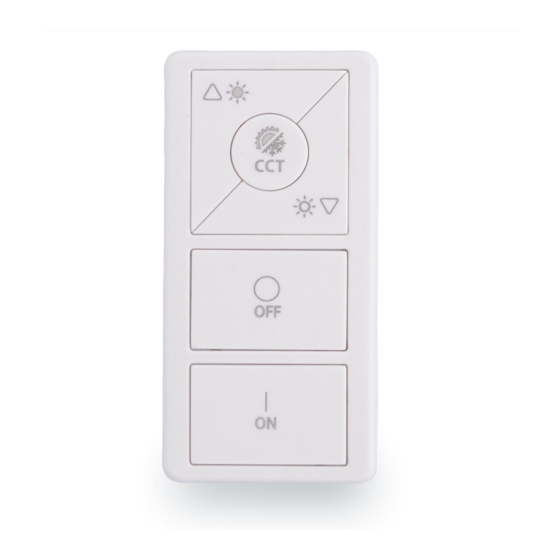
Catron V
Wireless 5 Button Remote
INSTALLATION AND QUICK START SHEET
WARNING AND GUIDELINES!!!
Read and follow all safety instructions!!
DO NOT INSTALL DAMAGED PRODUCT!
so that no parts should have been damaged during transit. Inspect to confirm.
Any part damaged or broken during or after assembly should be replaced.
WARNING : TURN THE POWER OFF AT THE CIRCUIT
BREAKER BEFORE WIRING
WARNING: Risk of Product Damage
Electrostatic Discharge (ESD): ESD can damage product(s). Personal grounding
equipment should be worn during all installation or servicing of the unit
Do not stretch or use cable sets that are too short or are of insufficient length
Do not modify the product
Do not mount near gas or electric heater
Do not change or alter internal wiring or installation circuitry
Do not use product for anything other than its intended use
WARNING - Risk of Electric Shock
Verify that supply voltage is correct by comparing it with the product
information
Make all electrical and grounded connections in accordance with the National
Electrical Code (NEC) and any applicable local code requirements
All wiring connections should be capped with UL approved recognized wire
connectors
All unused wiring must be capped
Product Overview
Catron V is a battery-powered switch that configures ON/OFF, intensity, and
Correlated Color Temperature of an individual or group of luminaires.
This compact device is designed for maximum longevity. It is part of Lumos
Controls ecosystem, which includes controllers, sensors, switches, modules,
drivers, gateways, and analytical dashboards.
INSTALLATION INSTRUCTIONS
Ensure optimal communications with other system components
Pick a convenient location, perhaps near a door where occupants enter and exit
Consider the construction materials in the space and remove the obstacles that
may interfere with RF signals
Installation Steps
Find a suitable place to fix the wall bracket using screws.
I. Using a level and a pencil, lightly mark 2 small dots to align the top edge of the
mounting plate.
II. Mark the mounting screw drill points and drill holes for the wall anchors with a
3/16" drill bit and insert wall anchors.
III. Insert the top screw(s) loosely and level the back plate.
IV. Insert the bottom screw(s), and then hand tighten the top screw(s).
V. Attach the wall plate on top of the rocker pad using the two screw holes.
This product has been properly packed
Do's
Installation should be performed by
a qualified electrician
Installation shall be in accordance with
all applicable local and NEC codes
Turn the power OFF at circuit
breakers before wiring
Observe the correct polarity of
output terminal
Specifications
Min
_
Input Voltage
2400
Frequency Range
Tx Power
6
Frequency Drift(Max)
-25
Frequency Deviation
±225
Carrier
_
30
Frequency Offset
_
Tx Current
Rx Current
_
Operating Temperature
0
Storage Temperature
-10
_
Relative Humidity
Receiver Sensitivity
-86
Dimension
105x40x12
Dimension
4.1x1.6x0.47
Required tools & supplies
Screwdriver
Screws
Don'ts
Don't use outdoors
Avoid input voltage exceeding
maximum rating
Don't dissemble the products
_
Type
Max
Remarks
3
3.3
VDC
CR 2032 battery
_
_
2483.5
MHz
_
8
dBm
Conductive
_
25
kHz
dF2
_
_
kHz
±275
_
150
kHz
Total current
_
48
mA
@MaxTx power
Total current @Rx
_
37
mA
mode
_
_
50
°C
_
_
60
°C
_
95
Non-condensing
%
_
_
-75
dBm
_
_
mm
L x W x H
_
_
in
L x W x H
Wall plates
Advertisement
Table of Contents

Related Manuals for WiSilica Lumos Controls Catron V


Summary of Contents for WiSilica Lumos Controls Catron V
- Page 1 Catron V Wireless 5 Button Remote INSTALLATION AND QUICK START SHEET Do’s Don'ts Installation should be performed by Don't use outdoors a qualified electrician WARNING AND GUIDELINES!!! Installation shall be in accordance with Avoid input voltage exceeding all applicable local and NEC codes maximum rating Read and follow all safety instructions!! Turn the power OFF at circuit...
- Page 2 Device Controls Intensity Operation...
- Page 3 Check if appropriate devices are linked Warranty 5-year limited warranty Please find warranty terms and conditions Note: Specifications may change without notice Actual performance can vary due to end-user environment and application +1 949-397-9330 All Rights Reserved WiSilica Inc...
Need help?
Do you have a question about the Lumos Controls Catron V and is the answer not in the manual?
Questions and answers