
Related Manuals for ATREYO AG-811


Summary of Contents for ATREYO AG-811
- Page 1 HARDWARE GUIDE AG-811 CCMS gateway with timer, 3 outputs and LTE www.atreyo.in Page | 1 ARAD/AG-811/HG/2021/02 – preliminary...
-
Page 2: Table Of Contents
Hardware Guide AG-811 Table of content 1. Introduction .......................... 3 1.1. Features ..........................3 1.2. Technical specification ....................... 3 2. Layout ........................... 4 2.1. Layout and connector functions ..................4 2.2. Dimensions ........................5 2.3. Packaging list ........................5 2.4. Optional accessory ......................5 3. -
Page 3: Introduction
Modbus devices. It can be controlled remotely from server or via SMS or also work in stand alone mode. The AG-811 has advance alert option with 10 mobile number list for SMS alerts. In superCap models there is power backup with power loss alert facility. -
Page 4: Layout
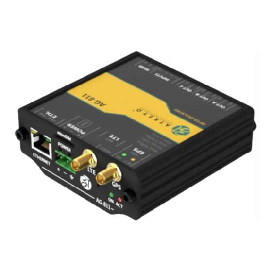
Hardware Guide AG-811 2. Layout 2.1. Layout and connector functions Top panel view Connector panel view www.atreyo.in Page |4 ARAD/AG-811/HG/2022/02 – preliminary... -
Page 5: Dimensions
Hardware Guide AG-811 2.2. Dimensions 2.3. Packaging list AG-811 gateway Antenna LTE and GNSS All necessary pluggable connectors DIN rail clamp with screws 2.4. Optional accessory High gain LTE antenna / panel mount combo antenna APS-10W24 – 3 phase power supply 24V/1A adapter power supply www.atreyo.in... -
Page 6: Connectors, Indicators And Functions
Hardware Guide AG-811 3. Connectors, indicators and functions 3.1. Multi-function reset button The AG-811 has multifunction reset button. This button is used to: • reset device • restart device • make default configuration Press and hold the reset button Behaviour... -
Page 7: Rs485 - Modbus
Hardware Guide AG-811 PIN number Function Remark DC + Power supply positive DC + Power supply positive Data DC - Power supply negative DC - Power supply negative 3.4. RS485 – Modbus The device has opto-isolated RS485 interface with support of Modbus RTU. It is dedicated to energy meter, voltage meter and any Modbus device like PLC which support Modbus RTU protocol. -
Page 8: Antenna
Hardware Guide AG-811 3.6. Antenna The device has two female SMA connector for LTE/GSM antenna and for GPS antenna. For proper working it is necessary to connect LTE + GSM band antenna and proper GPS antenna. Antenna line is 50Ω type. Do not switch on device without antenna connected. For better connectivity in remote area it is necessary to use high gain antenna and place it outside of electrical panel box. -
Page 9: System Functions
The device can upload configuration file from remote URL. The configuration of URL initially can be done by SMS or by internal website. Configuration details are specified in separate document – AG-811 Configuration Guide. 4.5. Power supply The device is powered by external DC power supply. Minimum supply voltage is 8V and maximum 36V. -
Page 10: Mounting Place And Condition
Hardware Guide AG-811 Supply Voltage Minimum A requirement Suggested power supply rating 1.5A 1.5A 0.5A 0.7A 0.5A 0.5A 4.6. Mounting place and condition The device is dedicated to use in environment that is clean and protected from water and dust. It can be used inside electrical panel boxes outdoor and without box in indoor application. -
Page 11: Wiring Example
Hardware Guide AG-811 5. Wiring example 5.1. Example 1 – with 24V external power relays/contractors This is simplified wiring diagram for control lighting with external high power DC24 coil relays. The inbuilt relays in the device drive with 12-24V DC external relays. The switches can be used for sending information to server about such cases like: open the door of panel, switching to manual option or any other. -
Page 12: Example 2 - With Common 230V Supply For Power Relays/Contractors
Hardware Guide AG-811 5.2. Example 2 – with common 230V supply for power relays/contractors The example with power relay/contactor powered by single 230V AC. In this example the separate power is provided for relays but common for all relays. www.atreyo.in Page |12 ARAD/AG-811/HG/2022/02 –... -
Page 13: Example 3 - With Separate Power For Relay/Contractor
Hardware Guide AG-811 5.3. Example 3 – with separate power for relay/contractor This example is with separate relay power. Each relay from different phase. www.atreyo.in Page |13 ARAD/AG-811/HG/2022/02 – preliminary... -
Page 14: Example 4 - Single Phase Direct Drive
Hardware Guide AG-811 5.4. Example 4 – single phase direct drive This is example for direct driving the load. Ensure maximum load not exceed 300W on every output. www.atreyo.in Page |14 ARAD/AG-811/HG/2022/02 – preliminary... -
Page 15: Legal
Hardware Guide AG-811 6. Legal 6.2. Trademarks Atreyo and the Atreyo logo are registered trademarks of Atreyo Research and Development LLP. 6.1. Copyright All other trademarks and copyrights are the property of their Copyright © 2022 Atreyo Research and Development LLP. This respective owners.
Need help?
Do you have a question about the AG-811 and is the answer not in the manual?
Questions and answers