Table of Contents
Advertisement
Quick Links
Operating Instructions
Light arrow / Light cross
(HLPK 9 LED)
Vertical lift light arrow
horizont group gmbh
Traffic Safety
Postfach 13 40
34483 Korbach
Homberger Weg 4-6
34497 Korbach
Germany
Light arrow HLPK 15 LED
Light arrow HLPK 13 LED
Light arrow HLK 9 LED
Vertical lift HLPK 15 LED
Collapsible light arrow
Telefon: +49 (0) 56 31 / 5 65 - 2 00
Telefax: +49 (0) 56 31 / 5 65 - 2 48
traffic@horizont.com
www.horizont.com
86274-15 (EN)
E - 09/2021
Advertisement
Table of Contents

Related Manuals for Horizont HLPK 15 LED


Summary of Contents for Horizont HLPK 15 LED
- Page 1 Operating Instructions 86274-15 (EN) E - 09/2021 Light arrow / Light cross (HLPK 9 LED) Light arrow HLPK 15 LED Light arrow HLPK 13 LED Light arrow HLK 9 LED Vertical lift HLPK 15 LED Vertical lift light arrow Collapsible light arrow...
-
Page 2: Table Of Contents
Original manual General safety instructions Light arrow / Vertical lift light arrow HLPK 15 LED, HLPK 13 LED, HLK 9 LED Meaning of pictograms Safety notes are characterised by pictograms. Safety instructions ..................... Additionally they are preluded by signal words, expressing the scale of the hazard. - Page 3 • is informed about the applicable health and safety regulations on site. In case of conversions or technical modifications which were not certified by horizont group gmbh, any war- • identifies additional hazards which might arise due to special working conditions at the operation site by ranty claims expire.
-
Page 4: Regular Maintenance
Check the light arrow for visible damage. Any use of the device beyond its intended use or any other use not in accordance with the inst- ructions may lead to dangerous situations for which horizont group gmbh does not assume any responsibility. -
Page 5: Short Product Description
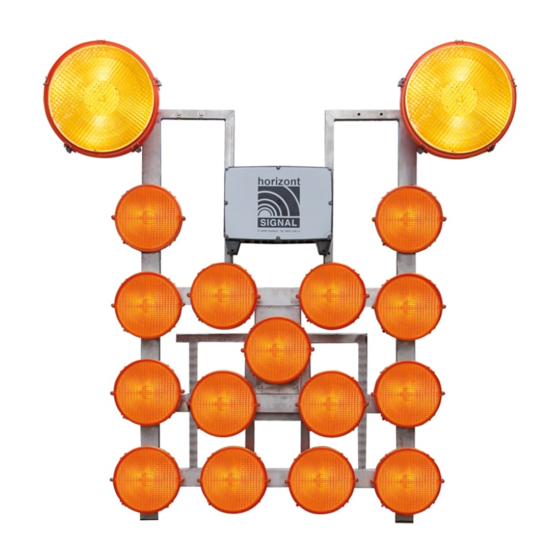
The circuit board can be removed after loosening the fixing screws, removing the spring connectors, loosening the motor cables and supply cable. Technical Data www.horizont.com Nominal operating voltage ..................12/24 V Max. operating volltage ....................30 VDC ARROW RIGHT (4) ARROW LEFT Min. - Page 6 BATTERY CONDITION INDICATION To switch on the control unit or the remote control in this state, press and hold the green > 12,1 V ( > 45% ) ON/OFF key pressed (see description below). yellow 12,1 V> Ubatt < 11,8V ( 20% - 45% ) <...
- Page 7 LED off additional lamps are de-activated When using additional lamps, you may only use horizont LED MS 340 lamps, which can work as halogen- imitating or flash- imitating lamps.
-
Page 8: Remote Control
Overview spare parts Pos. Part. no. Denomination 82220VP Main control unit HLPK 15 21021STGOE-1 Housing without electronics 21106LP-1HVP Cable remote control, 10m 21106LP-1FVP Radio remote control 82366 Charging cable with vehicle plug 82367-20M 20 metre cable with plug 25014 Rechargeable battery 12V/180Ah 925362 Housing MS340PLUS 82349... - Page 9 Accessory available on request (Radio remote control) LCD remote control With cable / radio connection: LED Remote control part no. 21157-08-0002 The light arrow can also be operated with other remote controls from the FA1 programme. These are available in different versions: Main screen LED remote control with cable: Artikel 21153-0003...
- Page 10 Wiring plan Light Arrow black schwarz function function display individual connection light sensor brown braun display Plug 1 end position Remote control/ 21106-LP-1x Plug 2 sensors (for LED & LCD orange orange (for radio (21153x/21154x/21157x) moduls ) yellow gelb green grün blue blau...
- Page 11 CAUTION! Self-diagnosis of the main controller and the system The self-monitoring of the security system does however not release you from the duty to con- The controller has extensive diagnostic features. Directly after switching on and during operation, the diagno- stantly ensure that it is functioning properly.
-
Page 12: Features
For part no. 210201-15x, 210502-09x and 210501-15x a supplementary set can be ordered. The additional advanced warning lights are going to be mounted to the lower part of the light arrow, see horizont group gmbh picture page 26 and overview on the electrical lifting and lowering device Division gerätewerk... - Page 13 Electronic lifting / lowering device Adjusting of the proximity switches (collapsible arrow) The proximity switches are pre-mounted, but should be checked for tight fit and correct limit switching points. The proximity switch for the position „Light arrow folded down“ is located at the fixed part of the lifting device at the height of the mounting plate for the light arrow.
-
Page 14: Adjusting The Proximity Switches
Mounting on flatbed vehicles (Vertical sliding arrow) Electronic lifting and lowering device (Collapsible arrow) Overview on different systems The vertical sliding arrow has been designed in such a way that it must be adequately secured both to the crossbars behind the driver‘s cab and to the platform floor. For this purpose, a sufficient number of fixing holes were drilled in the frame and on the base plate. - Page 15 Electronic lifting and lowering device (Vertical sliding arrow) Part no. 210201 - 15x Typ: HLPK15 210501 - 15x Typ: HLPK15 Part no. 21025 - 15x Typ: Vertical sliding arrow HLPK15 210502 - 09x Typ: HLK9 94414 Base frame 87399 Guiding pulley 94463 Collapsible frame 943452...
- Page 16 Wiring sequence of lamps HLK9 Connection plan (Lights > Main control) MS340 MS340 Left Right HLPK15 MS340 MS340 Left Right Illustration of the connection plan of the lights for remote control 21157 (LCD) On the LCD remote control, the lights are displayed with different codes. HLK13 For example, the R13 on the remote control shows light no.
- Page 17 Connection plan enclosure main control Cradle for the remote control (accessory item 88815VP ) HLPK15 Drilling plan and installation instructions ( Bottom view ) Cover for clipping in is enclosed Cable bushing rechargeable battery RS2000PLUS Nr.1 Mounting holes for mounting the cradle For adjusting the latching tension, ( Side view ) lift and move the lever...
Need help?
Do you have a question about the HLPK 15 LED and is the answer not in the manual?
Questions and answers