Table of Contents
Advertisement
Quick Links
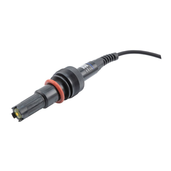
RESIDUAL CHLORINE SENSOR
(WATER QUALITY ANALYSIS)
User Manual for SRWQ100-YL105-9001
Thank you for choosing L-com product. To ensure safe, accurate performance and product
longevity, please take a moment to familiarize yourself with this manual before powering the
device. Please keep it handy for future reference. In case of any questions regarding the
installation or use of product, please call us at 800.341.5266.
Reach out to us at customerservice@l-com.com and visit our website at www.l-com.com
Signal Line
1
Advertisement
Table of Contents

Subscribe to Our Youtube Channel
Summary of Contents for l-com SRWQ100-YL105-9001
- Page 1 User Manual for SRWQ100-YL105-9001 Signal Line Thank you for choosing L-com product. To ensure safe, accurate performance and product longevity, please take a moment to familiarize yourself with this manual before powering the device. Please keep it handy for future reference. In case of any questions regarding the installation or use of product, please call us at 800.341.5266.
-
Page 2: Technical Indicators
Technical Indicators Measuring Range 0.00 20.00 mg/L (ppm) Accuracy 2% or ± 10 ppb HOCI Temperature Range 60.0 ˚C Response Time 90% less than 90 seconds Pressure Range 1 bar Shell Material ABS, 316 Output RS485, 4 20 mA Power Supply 30 VDC (Recommend 12V) Pipe Thread M 39*1.5... - Page 3 Electrode Outlet Procedure to Add Electrolyte and Replace the Membrane Head Kindly check the new membrane head is added with electrolyte before use. It is recommended to replace the electrolyte every three months. Also, it is subjected to the specific use of the measured medium and electrode.
-
Page 4: Electrode Polarization
Electrode Polarization Polarization Method: Put the electrode in the solution to be tested. Connect the power supply. Polarization starts as soon as the power is turned ON. Polarization Cases: The electrodes needs to be polarized in the following cases: When the electrode is first used, polarize it for more than 6 hours. - Page 5 During Immersion Installation During installation procedure, there will be frequent dirt on electrode, clean it regularly. Measuring value is not stable. Different insertion depths affects the measured value. The position of the electrode must be above the sediment. Electrode Communication Default Communication Instructions: ...
- Page 6 Read Floating Point Number Host Computer Transmission Format: Func- Register Start Qty. Of CRC16 Address tion Address Registers Code High High High Byte Byte Byte Byte Byte Byte Eg: Read 0x01 0x03 0x00 0x01 0x00 0x02 0xCB 0x95 Measured Value Eg: Read 0x01 0x03...
- Page 7 Write Floating Point Number Host Computer Transmission Format: Func- Register Qty. Of Register Data in CRC16 tion Start Registers Hexadecimal Floating Code Address Byte Point Number High High High Byte Byte Byte Byte Byte Byte 0x01 0x10 0x00 0x12 0x00 0x02 0x04 0x2A 0x63 Write Value...
-
Page 8: Calibration Instructions
Calibration Instructions Before Calibration: Write the residual chlorine calibration value to the sensor before calibration. If the calibration is 1.0 mg/L, write the current data to the 0x24 register (Floating point 1.0 to hexadecimal number is 3F800000, high and low transposition is 00003F80). ... - Page 9 Hosting Data Read/ Name Length Description Type Write Number Lower Limit Of Floating Lower limit of measurement value 0x 00 0C Measurement Point (4mA corresponding value) Upper Floating 0x 00 0E Upper temperature limit Temperature Limit Point Lower Floating 0x 00 10 Lower temperature limit Temperature Limit Point...
- Page 10 Common Instruction Examples Function Send command Return command Remarks Read The 2C814091 change order 01 03 04 2C 81 40 01 03 00 01 00 02 95 CB is 40912C81 and its floating measured 91 52 E7 point is 4.53 value Read The 723741DB change or-...
-
Page 11: Maintenance And Storage
Function Send command Return command Remarks Write device 01 06 00 19 00 02 01 06 00 19 00 02 D9 CC Set to 2 address D9 CC Write baud 01 06 00 1A 00 00 01 06 00 1A 00 00 A8 0D Set to 2400 rate A8 0D... -
Page 12: Modbus Troubleshooting
Troubleshooting If the measurement is not accurate, its mostly because the condition of residual chlorine electrode has changed. So it is necessary to check whether the residual chlorine electrode is in good condition or not. The residual chlorine electrode is not easy to damage, generally the membrane head may has dirt ,the electrolyte maybe polluted or lost etc., user needs to replace the membrane head or add / change electrolyte.

Need help?
Do you have a question about the SRWQ100-YL105-9001 and is the answer not in the manual?
Questions and answers