Advertisement
Available languages
Available languages
Quick Links
7965850COM
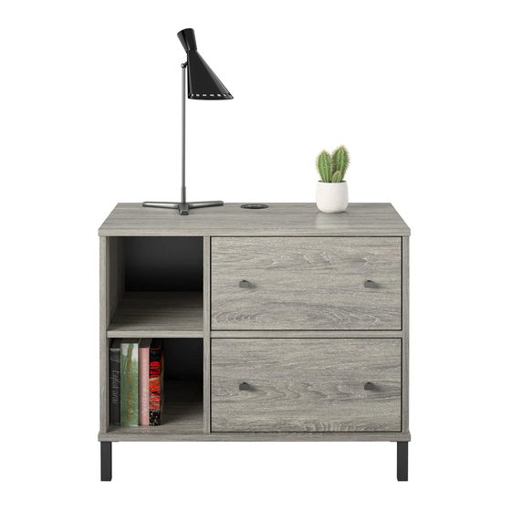
WIDE NIGHTSTAND
Date of Purchase ___ / ___ / ___
Lot Number:
THIS INSTRUCTION BOOKLET CONTAINS IMPORTANT SAFETY INFORMATION. PLEASE READ AND KEEP FOR FUTURE REFERENCE.
Secure Your Furniture
Keep your home and family safe
with the wall anchor kit that is
included with the product.
Serious or fatal crushing injuries can
occur from
g furniture.
WARNING: Manufacturer assumes no liability
for improper
on or excessive loads
placed on screws or bracket. This wall anchor
is not a subs tute for proper adult supervision.
Do Not Return This Product!
Contact our customer service team for help rst.
Call: 1-800-489-3351 (toll free)
Monday-Friday 9am - 5pm CST
Visit: www.ameriwoodhome.com
Easy
Assembly Di culty Meter
Follow Ameriwood Home
B347965850COM00MP
Tough
You
Tube
Advertisement

Subscribe to Our Youtube Channel
Related Manuals for Ameriwood HOME 7965850COM


Summary of Contents for Ameriwood HOME 7965850COM
- Page 1 Easy Tough Assembly Di culty Meter Serious or fatal crushing injuries can occur from g furniture. Follow Ameriwood Home WARNING: Manufacturer assumes no liability for improper on or excessive loads placed on screws or bracket. This wall anchor Tube is not a subs tute for proper adult supervision.
-
Page 2: Helpful Hints
Contact Us! Do NOT return this product! Contact our friendly customer service team t for help. Assembly Tips Call us! 1-800-489-3351 Monday-Friday 9am - 5pm CST Tube Visit ameriwoodhome.com to view the limited warranty valid in the U.S. and Canada. Helpful Hints PEOPLE NEEDED FOR ASSEMBLY: 1-2 ESTIMATED ASSEMBLY TIME: 45 MINUTES... -
Page 3: Before You Start
Before You Start Read through each step carefully and follow the proper order Separate and count all your parts and hardware Give yourself enough room for the assembly process Have the following tools: Flat Head Screwdriver #2 Phillips Head Screwdriver, Plier and Hammer. Cau on: If using a power drill or power screwdriver for screwing please be aware to slow down and stop when screw is ght. - Page 4 Not actual size TOP PANEL BOTTOM PANEL LEFT PANEL T7965850010 T7965850020 T7965850030 BRACE ADJUSTABLE SHELF T7965850060 T7965850070 PARTITION RIGHT PANEL T7965850050 T7965850040 This part is paperboard construc�on. It is not made from wood, but is required for the assembly of unit. (x2) (x2) (x2)
-
Page 5: Front View
Not actual size FRONT VIEW BACK VIEW This part is paperboard construc�on. It is not made from wood, but is required for the DRAWER assembly of unit. ameriwoodhome.com... -
Page 6: Part List
Hardware Bag Reference number : 27965850COM0MP Part List Not actual size 7 x 34mm Ø15 x 10mm 6 x 30mm Ø4 x 11mm (x4) (x8) (x2) (x2) (x14) (x16) TMP54520 TMP2531 TMP5101 TMP22620 TMP8002 TMP12120 Minifix Bolt Minifix Housing Drawer Bracket Cam Lock Cover Wood Dowel PWA Screw... - Page 7 STEP 1 (x2) (x2) TMP22620 TMP8002 Minifix Housing Wood Dowel - Install Minifix Housing (3) and Wood Dowel (4) into Brace (F) as below shown. Arrow facing outward ameriwoodhome.com...
- Page 8 STEP 2 (x2) (x8) TMP5101 TMP8002 Minifix Bolt Wood Dowel - Install Minifix Bolt (2) and Wood Dowel (4) into Right Panel (D) and Par��on (E) as below shown. ameriwoodhome.com...
- Page 9 STEP 3 (x4) TMP8002 Wood Dowel - Install Wood Dowel (4) into Le� Panel (C) as below shown. ameriwoodhome.com...
- Page 10 STEP 4 (x1) TMP84050 Safety Bracket Kit - Install Safety Bracket (12a) and (12b) to Top Panel (A) as show below. **do not fully �ghten this screw unfinished surface ameriwoodhome.com...
- Page 11 STEP 5 Quick Assembly Proper Oriental of CAM LOCK Recomm. 2 Persons - With another help to hold, Assemble Right Panel (D) and Par��on (E) with Brace (F) as shown below. unfinished edge unfinished edge unfinished edge unfinished surface ameriwoodhome.com...
- Page 12 STEP 6 Recomm. 2 Persons - With another help, Assemble Right Panel (D) and Par��on (E) with Top Panel (A) as shown below. - Turn the switch to lock. pre-drill nut turn switch to lock unfinished edge unfinished surface ameriwoodhome.com...
- Page 13 STEP 7 - Assemble Right Panel (C) with Top Panel (A) as shown below. - Turn the switch to lock. unfinished edge pre-drill nut turn switch to lock ameriwoodhome.com...
- Page 14 STEP 8 - Assemble Le� Panel (D), Right Panel (C) and Par��on (E) into Bo�om Panel (B) as shown below. - Turn the switch to lock. unfinished edge unfinished surface pre-drill nut turn switch to lock ameriwoodhome.com...
- Page 15 STEP 9 (x5) (x15) TMP21201 TMP22109 Metal Leg Leg Screw - Install Metal Leg(8) and Leg Screw (9) into Bo�om Panel (B) as shown. (x3) (x3) (x3) 9 (x3) 9 (x3) 9 ameriwoodhome.com...
- Page 16 STEP 10 (x28) TMP4703 Nail IMPORTANT! THE BACK PANEL IS A STRUCTURAL PART OF THIS UNIT AND MUST BE INSTALLED PROPERLY. With the help of another, carefully turn your unit over on its front side. Make sure the unit is square. Posi�on the back panel as shown.
- Page 17 STEP 11 - Flip the unit, turn to front of unit. TURN 90° TURN 180° ameriwoodhome.com...
- Page 18 STEP 12 (x4) (x8) TMP54520 TMP12120 Drawer Bracket PWA Screw - Install Drawer Bracket (5) to Drawer Front (H) using PWA Screw (6). - Repeat this step for other drawers. (x2) ameriwoodhome.com...
- Page 19 STEP 13 (x8) TMP12120 PWA Screw - Assemble Drawer Side ( I & J ) using PWA Screw (6) into Drawer Front (H). - Repeat this step for other drawers. (x2) ameriwoodhome.com...
- Page 20 STEP 14 (x8) (x4Sets) TMP21970 TMP40950 Drive Fastener T Knob Handle Set - Install Drawer Bo�om (K) into Drawer Side ( I & J ) and Drawer Front (H). - Install Drawer Back (L) using Drive Fastener (7) . - Install T Knob Handle Set (10a & 10b) to Drawer Front(H). - Repeat this step for other drawers.
- Page 21 STEP 15 - Flip the drawer, turn to front of drawer. TURN 90° (x2) ameriwoodhome.com...
- Page 22 STEP 16 For Masonry, Concrete, or other wall materials: Consult your local hardware store for appropriate anchors to securely attach the safety bracket. (x1) IMPORTANT: THIS UNIT MUST BE TMP84050 SECURE TO THE WALL TO HELP Safety Bracket Kit PREVENT TIPOVER. FOLLOW THESE hole INSTRUCTIONS TO INSTALL THE ANTI-TIPPING SAFETY BRACKET...
- Page 23 STEP 17 (x8) (x1) TMP2531 TMP26709 Cam Lock Cover Wireless Charger - Install Cam Cover Lock (1) to unit. - Push L Bracket to front and install Wireless Charger (14) follow by arrow. - Install drawer into body. close to lock...
- Page 24 STEP 18 (x4) TMP6001 Shelf Support - Install Shelf Support (13) into unit. Inside Adjustable Shelf (G) into body.
-
Page 25: Maximum Loads
Maximum Loads This unit has been designed to support the maximum loads shown. Exceeding these load limits could cause sagging instability product collapse and/or serious injury. 40 lbs 15 lbs 18.2 kg 6.8 kg 20 lbs 9.07 kg 15 lbs 6.8 kg 20 lbs 9.07 kg... - Page 27 - Antes de la instalación, asegúrese de que el interruptor de luz esté desbloqueado. Sistema de cierre Cam Lock (página 3) Este sistema de sujeción Cam Lock se utilizará durante todo el proceso de montaje. ** Si la posición del pasador está desplazada, use pinzas para sostener el interruptor basculante en posición vertical y gire con cuidado el interruptor de bloqueoal centro de la abertura.
- Page 28 Página 7 - Instale la carcasa Minifix (3) y el pasador de madera (4) en el soporte (F) como se muestra a continuación. Página 8 - Instale el perno Minifix (2) y el pasador de madera (4) en el panel derecho (D) y la partición (E) como se muestra a continuación.
- Page 29 Página 15 - Instale la pata de metal (8) y el tornillo de la pata (9) en el panel inferior (B) como se muestra. Página 16 Con la ayuda de otro, voltee cuidadosamente su unidad sobre su lado frontal. Asegúrese de que la unidad sea cuadrada.
- Page 30 Página 23 - Instale el bloqueo de la cubierta de la leva (1) en la unidad. - Empuje el soporte en L hacia el frente e instale el cargador inalámbrico (14) siguiendo la flecha. - Instale el cajón en el cuerpo. NOTA: Los orificios del soporte del cajón están ranurados.
- Page 31 Página 25 Página 26...
- Page 32 -Avant l'installation, assurez-vous que l'interrupteur d'éclairage est déverrouillé. ** Si la position de la broche est décalée, utilisez une pince tenir l'interrupteur à bascule en position verticale position et tournez prudemment le verrou au centre de l'ouverture.
- Page 33 Page 7 - Installez le boîtier Minifix (3) et le goujon en bois (4) dans le renfort (F) comme illustré ci-dessous. Page 8 - Installez le boulon Minifix (2) et le goujon en bois (4) dans le panneau droit (D) et la cloison (E) comme indiqué...
- Page 34 Page 16 IMPORTANT! LE PANNEAU ARRIÈRE EST UNE PARTIE STRUCTURELLE DE CET APPAREIL ET DOIT ÊTRE INSTALLÉ CORRECTEMENT A l'aide d'un autre, retournez délicatement votre appareil sur sa face avant. Assurez-vous que l'unité est carrée. Positionnez le panneau arrière comme indiqué. À l'aide d'un clou (11), fixez le panneau arrière (M) comme indiqué...
- Page 35 Page 23 - Installez le verrou de couvercle de came (1) sur l'unité. - Poussez le support en L vers l'avant et installez le chargeur sans fil (14) en suivant la flèche. - Installez le tiroir dans le corps. Page24 - Installez le support d'étagère (13) dans l'unité.
- Page 36 Page 25 Page 26...
Need help?
Do you have a question about the 7965850COM and is the answer not in the manual?
Questions and answers