
Subscribe to Our Youtube Channel
Related Manuals for Zünd PN Series


Summary of Contents for Zünd PN Series
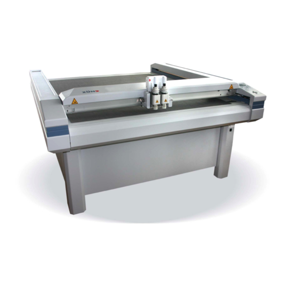
- Page 1 Digital flatbed cutter PN Series (S-800, M-800, M-1200, M-1600, L-800, L-1200, LR-1600, XL-800, XL-1200) Operating manual...
- Page 2 Original operating instructions Author Technical Editorial Department, Zünd Systemtechnik AG Composition and Zünd Systemtechnik AG publication © Copyright Zünd Systemtechnik AG Version: 4.11 Menu version: 11-2009 Date: 6010800ff Doc. no.:...
-
Page 3: Table Of Contents
PN series frame version Contents Introduction ..........1 Foreword . - Page 4 PN series frame version 3.11.2 Position of the safety signs ........11 Safety and monitoring devices .
- Page 5 PN series frame version Malfunctions ..........1 Troubleshooting for after-sales service .
- Page 6 PN series frame version 110002,001,11-2009, jmu...
-
Page 7: Introduction
PN series frame version Introduction Foreword Introduction Zünd Systemtechnik AG Altstätten, Switzerland Foreword Dear customer, By purchasing our product you are participating in the worldwide success of Zünd cutter systems. The modular design of our systems ensures: • A system solution that is suited to your individual requirements in terms of speed and quality •... -
Page 8: Using The Documentation
Introduction PN series frame version Using the documentation Using the documentation The instruction handbook supplied is intended to help you to: – Operate the machine safely – Perform routine machine maintenance – Use the machine optimally in all permitted areas To do this, you need to be able to find what you want within the documentation. -
Page 9: Symbols
PN series frame version Introduction Using the documentation 1.2.2 Symbols Illustration Close, fix, tighten, in Open, release, loosen, out Higher Lower Text structuring Task: Steps to perform Result: Outcome of the tasks performed. Prerequisites for performing a task List of tools Optional accessories There are a number of optional accessories available for the machine. -
Page 10: Points To Note When Reading This Operating Manual
Introduction PN series frame version Points to note when reading this operating manual Points to note when reading this operating manual Text references Chapter headings are numbered consecutively, with the first figure corresponding to the chapter number. Where reference is made to sections outside the current chap - ter, note the first figure and turn to the corresponding chapter, which contains the ci - ted section. -
Page 11: Current Status Of Documentation
PN series frame version Introduction Current status of documentation Current status of documentation Act accordingly to make sure that the documentation is complete and up-to-date at all times: – Do not remove parts of the documentation – Request copies of missing or illegible pages from the manufacturer, or download and print them from the Zünd homepage... - Page 12 Introduction PN series frame version Standardisation, tests, marking Directive 2006/42/EC and/or without CE marking. As a result, the declaration of con - formity must be issued again by the purchaser. 110003,001,11-2009, jmu...
-
Page 13: Legal Notice
Troubleshooting, hints and tips Important ! You can find information about troubleshooting and useful hints and tips on the Zünd homepage. (www.zund.com) Documented cutter models This documentation applies for the following types of PN series cutters. PN Series S-line M line L line... - Page 14 Introduction PN series frame version Publishing details 110003,001,11-2009, jmu...
-
Page 15: Product Description
PN series frame version Product description General Product description General This chapter contains information on the following: – Representational conventions in the operating manual – Possible uses of the machine – Structure of the main components – Important technical data –... -
Page 16: Product Identification
Product description PN series frame version Product identification Product identification Important ! The rating plate is used to uniquely identify your machine. Fig. 2-2 Position of rating plate 1 Manufacturer 6 Frequency 2 Machine type 7 Total weight 3 Serial number... -
Page 17: Overview
PN series frame version Product description Overview Overview Fig. 2-3 Overview 1 Beam 8 Side parts 2 Head carriage with tool head, right 9 Compressor side panelling 10 Electronics unit 3 Side panelling 11 Removable cover 4 Operating unit 12 Vacuum pump(s) -
Page 18: Layout And Function
Product description PN series frame version Layout and function Layout and function The cutter is constructed on a stable, welded frame construction. Upper cutter part The upper cutter part comprises: – Base frame with table – Beam with carriage –... -
Page 19: Intended Use
PN series frame version Product description Intended use Lower cutter part The lower cutter part comprises: – Side parts – Covering panels – Electronic unit and distribution box – Vacuum pump(s) The two side parts – Are attached to the base frame –... -
Page 20: Dimensions And Weights
Product description PN series frame version Technical information 2.7.1 Dimensions and weights Fig. 2-4 Dimensions Plotter line Type Working area * Overall dimensions Weight Material Clea- (W x L) approx. rance Width* S-line S-800 800 x 800 mm 1355 x 1246 x 995 mm... -
Page 21: Mains Connection
PN series frame version Product description Technical information 2.7.2 Mains connection Cutter Adjustable voltage 100 V, 115 V, 230 V (for electronics unit only) tolerance ± 10% Mains frequency 50/60 Hz Power consumption, one-phase(without 700 VA vacuum pump) Current consumption, one-phase(without... -
Page 22: Emissions
Product description PN series frame version Technical information Cutting performance Speed (axial) 1 - 1000 mm/s Addressable resolution 10 m/s 2.7.6 Emissions Noise Continuous sound pressure level for plotters < 80 dB (A) Depending on the tool system and materials to be processed –... -
Page 23: Safety
PN series frame version Safety General Safety General Your safety – as the operator, service engineer or otherwise – is the primary concern. Certain situations, problems or faults that may occur on the equipment could put your safety at risk if you are not aware of the steps you should take to avoid the resulting dangers. -
Page 24: Proper Use
Safety PN series frame version Proper use Proper use The proper use of the machine is essential for its safe operation. The equipment supplied: • Is listed and labelled • Determines the possible uses of the machine The machine is intended for use as an output device for CAD/CAM data for the la - belling and processing of materials arranged on the table. -
Page 25: Hazard Warnings, Important Instructions
PN series frame version Safety Hazard warnings, important instructions Hazard warnings, important instructions 3.4.1 Explanation of the hazard warning Both in the operating manual and on the device itself, dangers, important instructions and user tips are designated by special symbols and signal words as follows. -
Page 26: Structure Of The Hazard Warnings
Safety PN series frame version Hazard warnings, important instructions 3.4.2 Structure of the hazard warnings Example: Warning ! Risk of poisoning from the emission of toxic dust Processing certain materials can lead to the creation of toxic dust with significant risk to health. -
Page 27: Areas Of Responsibility
PN series frame version Safety Areas of responsibility Areas of responsibility The manufacturer • Is responsible for the safe condition of the machine on delivery, including instruc - tion handbook and accessories, according to the sales documentation. The owner or person authorised by him: •... -
Page 28: Rules And Safety At Work
Safety PN series frame version Rules and safety at work Rules and safety at work • The operation of the machine is always subject to local regulations regarding sa - fety at work and accident prevention. • Before the machine is put into operation: Always check the safety equipment and protective covers. -
Page 29: Danger Areas
PN series frame version Safety Danger areas Danger areas 3.9.1 Danger areas Fig. 3-1 Danger areas on the cutter 1 Tool head 4 Side covers near beam (openings) 2 Beam 5 Base plate (live parts) 3 Working area on table... -
Page 30: Danger Areas
Safety PN series frame version Danger areas 3.9.2 Danger area during processing Fig. 3-2 Danger area during processing 1 Danger area 110005,001,11-2009, jmu... -
Page 31: Danger Area During Initialisation
PN series frame version Safety Danger areas 3.9.3 Danger area during initialisation Attention ! Risk of injury during the manual initialisation of the tool. The safety devices are not active during the manual initialisation • Do not reach into the danger area during the manual initialisation •... -
Page 32: Working And Traffic Area
Safety PN series frame version Working and traffic area 3.10 Working and traffic area Warning ! There is a danger of injury to others through inappropriate behaviour or careless - ness. Please advise others to maintain an appropriate safety distance from the designated work and traffic zone. -
Page 33: Safety Signs
PN series frame version Safety Safety signs 3.11 Safety signs 3.11.1 Responsibility of the operator Warning ! Risk of injury due to a lack of safety signs Risks and sources of danger cannot be localised due to the lack of safety signs. - Page 34 Safety PN series frame version Safety signs Warning ! Safety risks due to missing or illegible safety signs Check all safety signs on a regular basis for legibility and completeness. Replace missing or illegible safety signs promptly with new original signs.
- Page 35 PN series frame version Safety Safety signs Warning signs – Are triangular and yellow-coloured – Are intended to draw attention to objects and circumstances which represent a potential danger to life and limb. Danger of hand injuries (crushing) Danger of hand injuries (severing)
-
Page 36: Safety And Monitoring Devices
Safety PN series frame version Safety and monitoring devices 3.12 Safety and monitoring devices Fig. 3-6 Safety and monitoring devices 1 Operating unit 4 Beam 2 On/off switch 5 Emergency stop switches 3 Light barriers on the ends of the... - Page 37 PN series frame version Safety Safety and monitoring devices – For emergency stops – For acknowledging keypad entries Emergency stop switches Emergency stop switches – Are integral parts of a safety circuit – Allow the machine to be switched off quickly in a dangerous situation...
-
Page 38: Personal Protective Equipment, Clothing
Safety PN series frame version Personal protective equipment, clothing 3.13 Personal protective equipment, clothing The safety equipment required for operating the machine is dependent on the fol - lowing factors: – The module and tool system – The material to be processed When operating the machine or carrying out maintenance or servicing work, wear close-fitting clothing and the appropriate personal protective equipment. -
Page 39: Mechanical Hazards
PN series frame version Safety Mechanical hazards 3.14 Mechanical hazards 3.14.1 Gathering, retraction Hazards caused by the bar, modules or the tool system during gathering and retrac - tion Possible consequences: • Cuts, bruising and crushing of fingers and hands •... -
Page 40: Cuts And Stab Wounds
Safety PN series frame version Risk of burns 3.14.3 Cuts and stab wounds Knives, routers and punching inserts have very sharp edges which are sometimes hidden by moving equipment (slipper spring). Possible consequences: • Cuts and stab wounds to the hands and arms... -
Page 41: Electrical Hazard
PN series frame version Safety Electrical hazard 3.16 Electrical hazard Warning ! Risk of death or injury from electric shock. The machine is operated with a mains voltage of 380 V, system frequency of 50/60 Safety instructions • Only trained service personnel are authorised to open switch boxes and electro - nics units. -
Page 42: Risks Arising From The Emission Of Toxic Dust
Safety PN series frame version Risks arising from the emission of toxic dust 3.17 Risks arising from the emission of toxic dust Warning ! Risk of poisoning from the emission of toxic dust Processing the most wide-ranging materials can lead to the creation of toxic dust with significant risk to health. -
Page 43: Environmental Hazard
PN series frame version Safety Environmental hazard 3.19 Environmental hazard Warning ! Processing residues, operating fluids etc. can cause damage and pollute the envi - ronment if they enter the soil, watercourses or the sewage system. Explanation of the hazard label... -
Page 44: Handling And Storage Of Chemicals
Safety PN series frame version Handling and storage of chemicals 3.20 Handling and storage of chemicals Warning ! Cleaning agents, operating fluids etc., can cause skin irritation and can therefore be hazardous to health if handled carelessly. Always wear personal protective equipment when working with chemicals. -
Page 45: Risk Of Fire And Explosion
PN series frame version Safety Risk of fire and explosion 3.21 Risk of fire and explosion Warning ! There is a risk of fire when routing and cutting inflammable materials Terminate the routing/cutting and leave the tool to cool in the case of •... -
Page 46: Danger Caused By Laser Beam (Laser Pointer)
Safety PN series frame version Danger caused by laser beam (laser pointer) In the event of a fire: • Switch off the machine (emergency stop switch) • Assess the situation: If the situation is dangerous, leave the area immediately and call the fire brigade. Only try to extinguish the fire if your personal safety is not at risk. -
Page 47: Safety Precautions For Service Personnel
PN series frame version Safety Safety precautions for service personnel 3.24 Safety precautions for service personnel The reliability, readiness and service life of the machine greatly depend on you car - rying out your work in a conscientious manner. Important ! Specialist knowledge and expertise are required to service and maintain the machi - ne. - Page 48 Safety PN series frame version Disposal 3-26 110005,001,11-2009, jmu...
-
Page 49: Controls And Operation
PN series frame version Controls and operation Controls Controls and operation Controls Fig. 4-1 Controls The control panel (Fig. 4-1, item 1) – Indicates the operating mode – Enables commands to be input and parameters set for the machine –... -
Page 50: Operating Modes
Controls and operation PN series frame version Operating modes Operating modes Initialisation After switching on the cutter system – Functions are checked using extensive self-tests – The control system determines the available tool head and material feeding sys - tem for the machine. -
Page 51: Operating Unit
PN series frame version Controls and operation Operating unit Operating unit Fig. 4-2 Operating unit 1 LCD display 8 PEN UP/DOWN key 2 Arrow keys 9 VACUUM key 3 Clear key 10 REF key (ZERO POINT) 4 Escape key 11 ONLINE key... -
Page 52: Description Of Keypad
Controls and operation PN series frame version Operating unit 4.3.1 Description of keypad The keypad on the operating panel is used to enter all commands, parameters and settings for cutter operation. The keypad is divided into the following functional blocks: •... - Page 53 PN series frame version Controls and operation Operating unit – To preset, indicate or delete a user-defined reference point – To enter X/Y coordinates. Online key (11) This key is used for switching between ONLINE and OFFLINE mode. Direction keys (12) Depending on the particular mode, these keys have the following functions: In ONLINE mode, pressing one or more direction keys triggers an emergency stop.
-
Page 54: Description Of The Display
Controls and operation PN series frame version Operating unit 4.3.2 Description of the display The four-lined LCD – Indicates mode, errors and failures – Shows the moving display, the standard menu and the command menu. The moving display appears after –... -
Page 55: Setting The Language
PN series frame version Controls and operation Operating unit Less commonly used functions are activated via the command menu (see point 5.4 "Command menu"). 4.3.4 Setting the language The cutter system – Has a user interface in different languages –... -
Page 56: User-Defined Function Keys
Controls and operation PN series frame version Operating unit 4.3.6 User-defined function keys Frequently used functions and commands are assigned to the function keys F1 - F4 by the manufacturer (see user parameters). The programming for the function keys –... - Page 57 PN series frame version Controls and operation Operating unit Tabelle 1: Parameters Usr: 1 Usr: 2 Usr: 3 Usr: 4 Usr: 5 Usr: 6 Usr: 7 Usr: 8 Usr: 9 ZOOM X 1.000 1.000 1.000 1.000 1.000 1.000 1.000 1.000 1.000...
- Page 58 Controls and operation PN series frame version Operating unit Tabelle 1: LINK TO TOOL (Press. swit - ching) LINK TO TOOL (Trailing knife) LINK TO TOOL (Spec. Pen - pulse) FRE - QUENCY (Laser) RECESS POWER (Laser) MAX. POWER (Laser)
- Page 59 PN series frame version Controls and operation Operating unit Tabelle 1: USER STAN - Plot FAST MEDI DARD quik - slowly rou - (Userstring) ting rou - rou - fast mediu slow ting ting Parameters Usr: 1 Usr: 2 Usr: 3...
-
Page 60: Command Menu
Controls and operation PN series frame version Command menu Command menu 4.4.1 General All available commands are contained in a command menu. The command menu has a user-friendly layout: • Frequently used commands can be found at the start of the menu. -
Page 61: Menu Structure
PN series frame version Controls and operation Command menu 4.4.2 Menu structure The menu is structured in tree form. Related and similar functions are combined to form groups. The basic level contains five groups: Job setup Settings for the JOB (configuration); e.g. speed, deceleration, initialisation. -
Page 62: Service Mode
Controls and operation PN series frame version Command menu Inputs of numbers If a flashing cursor appears above a number an input is required: Enter the desired number using the numerical keys and confirm with ENT key. Pressing the ESC key during input returns the display to the basic level without sa - ving the input. -
Page 63: Command Description
PN series frame version Controls and operation Command description Command description The menu commands and parameters described below are not available for all plot - ter modes and some may not be released for use. Menu commands that are not... - Page 64 Controls and operation PN series frame version Command description XY-UP (1122) Acceleration with raised tool. Accelera- Universal version Speed version tion levels 0.125 x a 1.25 m/s 0.25 x a 2.5 m/s 0.5 x a 5 m/s 10 m/s Acceleration levels: –...
- Page 65 PN series frame version Controls and operation Command description CONNECT PU/PD (1145) This function is to be used only in conjunction with a laser engraving system. Delays are entered in milliseconds (ms). The setting range is from 1 - 9999 ms.
- Page 66 Controls and operation PN series frame version Command description QUALITY (1171) Possible settings: HIGH/MEDIUM/LOW/4/5/6/7/8/9 Default:MEDIUM The "HIGH" quality level should always be selected for short texts with high quality requirements. Make the setting either via: – The arrow keys (left/right) or –...
- Page 67 PN series frame version Controls and operation Command description Tz-MODULE (118) All functions and settings within this submenu are relevant only for tool head type Tz. The following commands are described in section 3 in the specifications for the Tz head.
- Page 68 Controls and operation PN series frame version Command description Make the setting either via: – The arrow keys (left/right) or – The numeric keypad: 0 = AUTO, 1 = ON, 2 = OFF Confirm the entry using the ENT key.
- Page 69 PN series frame version Controls and operation Command description The "Standard" settings for a "Marker" are as follows: MODE NO VACUUM (128) ROLL OFF CORE (1291) FIXING CLAMP B. (1293) ROLL-UP CORE (1294) The "Standard" settings for a "Cutter" are as follows:...
- Page 70 Controls and operation PN series frame version Command description SHEET FEEDER (126) The commands in this submenu are used to configure the sheet feeder (autom. sheet feeding). This can be operated in various ways. MODE (1261) Here, it is possible to select between the various loading methods.
- Page 71 PN series frame version Controls and operation Command description MODE (128) This command: – Is valid only for plotter types "Marker" and "Marker/Cutter" used in the textile in - dustry – Defines the feed cycle for the material feeding system Possible settings: VACUUM, VAC + STOP, NO VAC With VACUUM, the material is held down by vacuum.
- Page 72 Controls and operation PN series frame version Command description SENSORS (1292) This command defines material monitoring with foil sensors. Possible settings: 4x / 1x / NONE Setting Material monitoring 4 foil sensors for automatic foil feeding with fixed feeder elements.
- Page 73 PN series frame version Controls and operation Command description • Save as a user parameter, if required. GEOMETRY (14) There is a geometric means of cutting a job (Cut-File) at a certain angle when using the plotter. As a precondition, the job may not include any feed and the size of the Cut-file may not exceed 1 MB.
- Page 74 Controls and operation PN series frame version Command description 4.5.2 Tool (2) SELECT TOOL (21) A specific tool can be selected using the commands within this submenu. NUMBER (211) A tool can be selected here. Possible inputs: 1, 2, 3, 4 Enter the tool number using the numeric keypad and confirm with the ENT key.
- Page 75 PN series frame version Controls and operation Command description OSCILLATING TOOL (222) The following settings are valid for electrical oscillating tools (EOT) and for pneumatic oscillating tools (POT). DELAY (2221) Sets the delay parameter for the tool's downward movement. Parameters are scaled in 1/10 seconds.
- Page 76 Controls and operation PN series frame version Command description E.g.: POT - module 1, DRT - module 2 LINK TO TOOL (2222) LINK TO TOOL (2312) POT & DRT/EOT (2224) = ON POT & DRT/EOT (2224) = OFF LASER (223) The commands in this submenu are valid only in conjunction with a laser system.
- Page 77 PN series frame version Controls and operation Command description Possible inputs: 0, 1, 2, 3, 4 Tool number: – Enter using the arrow keys (left/right) or the numeric keypad. – Confirm with the ENT key. – Save as a configuration parameter, if required.
- Page 78 Controls and operation PN series frame version Command description ROTATIONAL SPEED Select high or low frequency for the DRT. (2313) Setting HIGH 20000 12000 NOTCH TOOL (232) The notch tool consists of two rotating tools and can be used, depending on the tool application, as a punch tool (for drilling) or as a groove tool (to cut out V-shaped groo - ves).
- Page 79 PN series frame version Controls and operation Command description PART MARKER (235) Settings for the "Part Marker" tool - an inkjet print head to label/mark parts or com - ponents. LINK TO TOOL (2351) The module of the tool into which the Part Marker is inserted has to be selected here.
-
Page 80: Tool (2)
Controls and operation PN series frame version Command description As a final check, carry out a test cut with the functions 2431 and 2432 resp. Corrections can be made for all tools separately (tools 1-4). When all tools are pro - perly set up, save the configuration parameters (46). - Page 81 PN series frame version Controls and operation Command description TOOL MANAGER (25) The tool manager facilitates the initialisation and setup of frequently used tools by sa - ving important settings and initialisation processes for each individual tool. Every tool for which a parameter set has been saved in the tool manager can be made ready for operation simply by accessing the relevant parameters.
-
Page 82: Functions (3)
Controls and operation PN series frame version Command description 4.5.3 Functions (3) TEST-CUT (3) Attention ! This command may be used only with tangentially controlled tools (knives). Using other tool heads could result in damage to the worksheet, tool and the surface of the table. - Page 83 PN series frame version Controls and operation Command description MOVEMENT POSSIBLE Switch to ONLINE by pressing either the ENT, CE, ESC or ONLINE key. Attention ! Danger from automatic starts After switching to ONLINE, the machine moves to the reference point and immedia - tely starts processing data.
- Page 84 Controls and operation PN series frame version Command description DEFINE (342) The window range is determined here by entering two reference points on the wor - king surface. Procedure Using the direction keys, move the tool head to the lower right corner of the desired window range and press the ENT key.
- Page 85 PN series frame version Controls and operation Command description • Position a DIN A4 sheet on the table, at a right-angle to the X direction and fix it. • Position the pen on the lower left corner of this sheet. Then press the REF key, set a reference point and confirm with the ENT key.
- Page 86 Controls and operation PN series frame version Command description MORE (39) REFERENCE (391, REF) This submenu contains commands for setting and displaying up to two reference points (starting points) on the working area. It can be beneficial to have a second re - ference point available for some specific applications.
- Page 87 PN series frame version Controls and operation Command description Double-sided mode The selected axis (X or Y ) is mirrored when you switch to double-sided mode. For this application, it is necessary to mark or fix the position of the material.
- Page 88 Controls and operation PN series frame version Command description GO REFERENCE 2 (3916) The machine moves to reference point no. 2. MODE (3918) Switches from tandem to double-sided ref. mode. DBL REF MOD (39181) TANDEM Tandem mode is activated (= default).
- Page 89 PN series frame version Controls and operation Command description At the end of the feed movement, the valve and the vacuum pump/blower are toggled on again providing a slow, not sudden, build up of vacuum that prevents folds from forming in the material.
-
Page 90: User (4)
Controls and operation PN series frame version Command description Vac pump is [on/off] On/Off vacuum pump Vacuum is on Intake/exhaust by switching valve Exit Park Exit submenu and park position The park position can be cancelled using numerical key '3' only. When this is done, the head moves to the last position from before the PARK command. - Page 91 PN series frame version Controls and operation Command description NUMBER (411) Enter the number (1-9) of the desired user parameter group: – Use either the arrow keys (left/right) or the numeric keypad. – Confirm with the ENT key. SAVE (42) This command stores the current settings for the commands mentioned above as a user parameter group.
- Page 92 Controls and operation PN series frame version Command description F2 KEY (452) F3 KEY (453) F4 KEY (454) REF KEY (455) VAC KEY (456) The new assignment of function keys must then be saved as a user parameter. The machine must be restarted in order to change the current function key assign - ment.
-
Page 93: Basic Setting (5)
PN series frame version Controls and operation Command description 4.5.5 Basic setting (5) SERIAL LINK (51) This submenu contains commands for setting up and monitoring data transmission. BAUD (511) Used to set the Baud rate between 600 and 38,400 Baud. - Page 94 Controls and operation PN series frame version Command description MODE (53) LANGUAGE (531) The commands in this submenu enable you to display the user interface in the fol - lowing languages: Select the desired language: – Using the arrow keys (left/right) –...
-
Page 95: Operating The Cutter
PN series frame version Controls and operation Operating the cutter Operating the cutter 4.6.1 Checks before switching on • Are there any objects (tools, etc.) on the table and side covers? Attention ! Light barriers and the safety shut-down are not active during initialisation. -
Page 96: Setting Up
Controls and operation PN series frame version Operating the cutter 4.6.3 Setting up Attention ! Danger of injuries through uncontrolled movements of the beam and tool head in ON-LINE mode. Carry out all setup work for the cutter system in OFF-LINE mode only! You can find all necessary information about setting up the tool and the material fee - ding system in sections 3 and 4. -
Page 97: Malfunctions
PN series frame version Malfunctions Troubleshooting for after-sales service Malfunctions Troubleshooting for after-sales service If cutter system failures occur and you need our after-sales service, make a note of: – The machine's serial number – The error number indicated on the operator panel including the complete error message (press ENT key several times for request). -
Page 98: Error Messages
Malfunctions PN series frame version Error messages Error messages If the operating panel shows an error message: • Remove the cause of error • Confirm the error message with the ENT key The cutter system will then proceed in the ON-LINE mode or give you more informa - tion on the display about how to rectify the error. - Page 99 PN series frame version Malfunctions Error messages 0301 AC fault X-Override Causes X-axis blocked or pushed out of its setting position Action Try to reinitialise the plotter. If this is not possible, switch off the plotter and check the X-axis Hint Check the position sensor using test function 52.
- Page 100 Malfunctions PN series frame version Error messages 0317 AC zero mark X Permanent light Causes X-axis zero mark sensor is defective (permanent light), defect on C-board or interruption between C-board and master board. Action Troubleshooting: see chapter "Zeromarks" for more information.
- Page 101 PN series frame version Malfunctions Error messages 0801 Emergency stop <ENT> to reinit Hint See chapter "Emergency stop" in the description of the electronics. It is usu - ally possible to carry out a software reinitialisation if the external emergency stop print no.
- Page 102 Malfunctions PN series frame version Error messages 1002 Check axis tool T or Z is faulty Cause The head recognised requires an axis (T- or R-axis) for which an error was determined after power up (check axes).=> Axis problem or wrong head recognition.
- Page 103 PN series frame version Malfunctions Error messages 1602 Airpressure Check Airpressure failed Cause Compressed air monitoring was activated. Low air pressure detected for the vacuum zones (LC-16/... type cutters) or for the foil cover brakes (LC-27/ 32T). Action Check whether compressed air is available and whether the pressure that has been set is correct.
-
Page 104: Failures In The Distribution Box
Malfunctions PN series frame version Failures in the distribution box Failures in the distribution box Error description On/Off switch in pos. 'I' – Plotter system does not function. LCD on operator panel dark. – Machine is operating, but not the following units: •... - Page 105 PN series frame version Malfunctions Failures in the distribution box Warning ! Risk of injury from unauthorised maintenance. Before maintenance, disconnect all power supplies to secure the machine against unauthorised start-up. (There is more than one power supply) Check fuses in the distribution box.
- Page 106 Malfunctions PN series frame version Failures in the distribution box 110/115 V 12.5 A slow-blow, Ø 5 x 20 AC input electronic unit AC input compressor Mains input for vacuum pump AC current Fuse specifications 230 V, 50 Hz 16 A SPT, Ø 5 x 20 mm, high...
-
Page 107: Electronic Box Fuses
PN series frame version Malfunctions Electronic box fuses Electronic box fuses Attention ! Danger of injury by electric shock Always remove all power cables from the mains before handling any live components of the cutter! Inspect/replace fuses Loosen the fuse holder carefully using a screwdriver and remove it from the housing (see illustration) Remove the fuses from the fuse holder, inspect them and replace as necessary. - Page 108 Malfunctions PN series frame version Electronic box fuses Replacement fuses Fuse holder with 2 fuses AC current Fuse specifications 230 V 4 A slow-blow, Ø 5 x 20 mm 100/115 V 8 A slow-blow, Ø 5 x 20 mm 5-12...
-
Page 109: Cleaning And Maintenance
PN series frame version Cleaning and maintenance General Cleaning and maintenance General – This chapter describes (in tabular form) all the maintenance jobs which are re - quired for the machine. – The maintenance list only affects the basic unit. Maintenance activities for mo - dules, tool inserts and options can be found in the respective operating manual. -
Page 110: Safe Maintenance Of The Machine
Cleaning and maintenance PN series frame version Safe maintenance of the machine Safe maintenance of the machine General safety instructions • Servicing and repair work must be carried out by trained specialist personnel. • For periodic checks/inspections you must comply with the mandatory intervals or the intervals specified in the instruction manual. -
Page 111: Operating Resources
PN series frame version Cleaning and maintenance Operating resources Operating resources 6.3.1 Handling operating materials Following the instructions for handling operating materials carefully will increase the reliability and service life of the machine. Follow the regulations for handling chemicals, particularly cleaning fluid and lubri - cants. -
Page 112: Cleaning Fluids
Cleaning and maintenance PN series frame version Operating resources 6.3.2 Cleaning fluids Attention ! The use of incorrect cleaning fluids not approved by Zünd will damage the machine. Only use cleaning fluids recommended by Zünd Systemtechnik. Do not use abrasive cleaning fluids. Caustic substances and scouring agents can da - mage surfaces of the cutter (e.g. -
Page 113: Steps For Maintenance
PN series frame version Cleaning and maintenance Steps for maintenance Description Specification Advanced Performance NI100 Instant Adhesive Steps for maintenance Different types of symbols (circle, box, star – solid; circle, box, star – outline) divide the service and maintenance tasks into two groups. - Page 114 Cleaning and maintenance PN series frame version Steps for maintenance Maintenance/inspec- Work to be carried out tion in Operating hours by personnel by authorised maintenance personnel one-off activity one-off activity repetitive interval repetitive interval when necessary when necessary General Visually check the machine for damage...
- Page 115 PN series frame version Cleaning and maintenance Steps for maintenance Maintenance/inspec- Work to be carried out tion in Operating hours by personnel by authorised maintenance personnel one-off activity one-off activity repetitive interval repetitive interval when necessary when necessary Check alignment of toothed/steel belt and readjust if necessary...
-
Page 116: Maintenance Jobs
Cleaning and maintenance PN series frame version Maintenance jobs Maintenance jobs 6.5.1 Maintenance position Warning ! Danger of injury The cutter may be put into operation by third parties. • Always place the cutter in the maintenance position before carrying out mainte -... - Page 117 PN series frame version Cleaning and maintenance Maintenance jobs • Regularly (daily) remove all materials residues from the table, the tools and mo - dules. • Keep the environment clean (free from material residues, dust). 110010,001,11-2009, jmu...
-
Page 118: Instructions For Disposal
Cleaning and maintenance PN series frame version Instructions for disposal Instructions for disposal Important ! Contact Zünd customer services or your service partner before you dispose of your cutter. Zünd cutters are modern industrial devices which correspond with the current stan - dards and guidelines on the disposal of old appliances. -
Page 119: Transport And Storage
PN series frame version Cleaning and maintenance Transport and storage Transport and storage 6.8.1 General For shipment, the tool plotter is either – Completely pre-assembled, secured on a wooden pallet and packaged in a woo - den crate – Dismantled into the upper part of the plotter, side parts and accessory equipment (if it is difficult to get to the installation site). -
Page 120: Accessories, Spare And Wearing Parts
Cleaning and maintenance PN series frame version Accessories, spare and wearing parts Accessories, spare and wearing parts 6.9.1 Supplied accessories The accessory equipment case contains: – Teflon-based lubricant – – 1 brush – Back-up fuses for the distribution box (5 for each required rating) –... -
Page 121: Information On Installation And Commissioning
PN series frame version Cleaning and maintenance Information on installation and commissioning 6.10 Information on installation and commissioning The cutter system may only be installed and commissioned by • Expert personnel from the manufacturer • Personnel who have been trained and authorised by the manufacturer Important note for The cutter system is delivered with a preset mains voltage. - Page 122 Cleaning and maintenance PN series frame version Information on installation and commissioning Fig. 6-1 Set the voltage 1 Holder 3 Fuse holder 2 Set voltage (230/115/100 V) 4 Fuse – Set the voltage selector of the electronics unit to the available mains voltage.
-
Page 123: Tools
PN series frame version Tools Tools 100011,003,11-2009, jmu... - Page 124 Tools PN series frame version 100011,003,11-2009, jmu...
-
Page 125: Tool Heads
PN series frame version Tool heads Tool heads 110008,001,11-2009, jmu... - Page 126 Tool heads PN series frame version 110008,001,11-2009, jmu...
-
Page 127: Options
PN series frame version Options Options 100015,001,11-2009, jmu... - Page 128 Options PN series frame version 100015,001,11-2009, jmu...
-
Page 129: 10 Material Feed
PN series frame version Material feed 10 Material feed 10-1 100012,003,11-2009, jmu... - Page 130 Material feed PN series frame version 10-2 100012,003,11-2009, jmu...
-
Page 131: 11 Additional Specifications
PN series frame version Additional specifications 11 Additional specifications 11-1 100014,003,11-2009, jmu... - Page 132 Additional specifications PN series frame version 11-2 100014,003,11-2009, jmu...
-
Page 133: 12 Documents
PN series frame version Documents 12 Documents 12-1 100017,001,11-2009, jmu... - Page 134 Documents PN series frame version 12-2 100017,001,11-2009, jmu...
-
Page 135: 13 Annex
PN series frame version Annex After-sales Service 13 Annex 13.1 After-sales Service Responsible service point: Machine number: Important default settings: Modifications: Interface parameters: Date of initial commissioning: Responsible service engineer: Signature 13-1 100013,003,11-2009, jmu... - Page 136 Annex PN series frame version After-sales Service Acceptance certificate from customer: Date Signature 13-2 100013,003,11-2009, jmu...
-
Page 137: Service And Maintenance Works
PN series frame version Annex Service and maintenance works 13.2 Service and maintenance works In order to conserve the value of your plotter system, carry out one service per year. All service, maintenance and repair works must be entered and confirmed into the table below by the service technician. - Page 138 Annex PN series frame version Service and maintenance works Date/Signature Remarks 13-4 100013,003,11-2009, jmu...
- Page 139 PN series frame version Annex Service and maintenance works Date/Signature Remarks 13-5 100013,003,11-2009, jmu...
- Page 140 Annex PN series frame version Service and maintenance works Date/Signature Remarks 13-6 100013,003,11-2009, jmu...
- Page 141 PN series frame version Annex Service and maintenance works Date/Signature Remarks 13-7 100013,003,11-2009, jmu...
- Page 142 Annex PN series frame version Service and maintenance works 13-8 100013,003,11-2009, jmu...
Need help?
Do you have a question about the PN Series and is the answer not in the manual?
Questions and answers